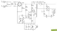
Unfortunately, the schematic is missing. R4, R5, R6, the keying transistor F3NK80Z converters, diodes in the rectifier bridge and the V8 diode were burnt in the charger. Despite the replacement of components, the charger still does not work. Does anyone have any suggestions why the inverter does not start? After disconnecting the secondary taps of the transformer and loading it with a small bulb, the voltage on the secondary side does not appear. What is the working principle of the charger inverter?
Should the top contacts of the battery and the bottom contacts of the battery have the same potentials? (are they duplicated). After connecting the meter to the charging contacts - no voltage. The screwdriver works normally on the upper contacts.
The integrated circuit is mounted on the secondary side of the inverter:
075022221
7B416277
V6 G4 PHL
What's with the layout? There is no information on google
In addition, the following system works on the secondary side:
LM324AN


