Hello,
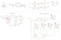
I am asking colleagues to look at the eagle diagram of the system that measures 5 temperatures through PT100 sensors (in the schematic as an X3 connector) and a 2-channel 0-10V voltmeter.
First of all, I am interested in the issue of PT100. Do you have any suggestions for such a connection? Maybe you can somehow simplify the connection? The current from LM334 should be equal to 1mA. By design, the system is to be composed of elements available in the PL, therefore any hard-to-reach ready-made chips under PT100 are dropped.
Any suggestions for the layout are welcome.
Will I be able to get a 0.1st resolution in such a successful arrangement?
Thank you in advance for your response.


