logo elektroda
logo elektroda
X
logo elektroda

Verifying ESP8266 Temperature Controller Wiring Diagram

joker0skater 621 9
ADVERTISEMENT
Treść została przetłumaczona polish » english Zobacz oryginalną wersję tematu
  • #1 19407308
    joker0skater
    Level 8  
    Hello
    I hope I have put the topic in the right subforum.
    I am in the process of constructing a temperature controller based on ESP8266.
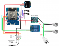
    I am a layman when it comes to electronics, I have read a bit and want to solder it as follows. If anyone finds a spare moment please verify the connections drawn out and point out any errors.

    Verifying ESP8266 Temperature Controller Wiring Diagramrys.png Download (513.71 kB) .
  • ADVERTISEMENT
  • #2 19407313
    cuctu_P
    Level 9  
    One more question, is the probe analogue or digital?
  • ADVERTISEMENT
  • #4 19407435
    Hawajek
    Level 24  
    Once you've soldered it up, remember that you still need a program under which it will all work. Do you have any experience with programming, uploading programs etc?
  • ADVERTISEMENT
  • #5 19407465
    cuctu_P
    Level 9  
    In my opinion, these green wires should go to similar pins due to the fact that this is a digital sensor. If you connect it this way it is unlikely to work and you have a lot of pins.
  • #6 19407527
    robiw
    Level 26  
    cuctu_P wrote:
    In my opinion these green wires should go to similar pins due to the fact that this is a digital sensor. If you connect it this way it is unlikely to work and you have a lot of pins.


    Wrong. They should be connected together. They are sensors on the 1-wire bus.... R
  • #7 19407710
    Slawek K.
    Level 35  
    cuctu_P wrote:
    In my opinion these green wires should go to similar pins due to the fact that this is a digital sensor. If you connect it this way it is unlikely to work and you have a lot of pins.
    .
    They don't have to, but they can too, in which case you need to create separate instances for OneWire.

    Greetings
  • #8 19407929
    robiw
    Level 26  
    Exactly, although there is usually no reason to create several 1-wire buses within a single project, given that the bus provides chip addressing. But on a stubborn basis one can split ;-) .... R
  • ADVERTISEMENT
  • #10 19417623
    joker0skater
    Level 8  
    Thank you very much for your answers.

    Hawajek wrote:
    After you have soldered it, remember that you still need a program under which it will all work. Do you have any experience with programming, uploading programs etc?
    .

    I do not have, I will rely on the source: http://vito.tw/?p=460

Topic summary

The discussion revolves around verifying the wiring diagram for a temperature controller based on the ESP8266. The original poster seeks confirmation on their connections, particularly regarding the type of temperature probe used (analog or digital). Responses highlight the importance of proper wiring, especially for digital sensors, and the necessity of programming the ESP8266 after soldering. There is a debate on whether multiple 1-wire buses are needed, with suggestions that a single bus can suffice due to chip addressing capabilities. The conversation also includes a link to a product related to the project.
Summary generated by the language model.
ADVERTISEMENT