Hello,
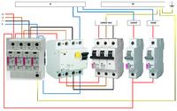
Recently, I changed the old single-phase connection to a three-phase so-called strength. But after connecting several protections, the residual current device trips automatically. I don't know what could be the cause and I am full of hope that someone here will help me. In a moment I will put below the diagram that I made and which I used at home when connecting.
I would like to mention that the house has an old installation made of copper, but without PE protection, and therefore in three sockets zero-bridging with a protective pin was used. During the test, the devices from these sockets were disconnected to be sure that the differential would not be turned off automatically. Unfortunately, the security was released.
Diagram:

Is the connection according to this diagram correct?
Do i need to correct anything?
Currently I had to disconnect the zero connected from the differential to the strip and I led from the surge arrester (where the main zero is connected) to the strip - because if there was no light I need to have at home, but you know the residual current switch does not protect, at least at home where you would have to lead one the core of the PE cable to the sockets.
The problem arises with the garage where there are several power sockets where the protective conductor is led.
How to find out what is the cause?
He can disconnect the zero going to the garage and check if the residual current device will trip.
Then plug this zero back in and disconnect the zero going home and check if it breaks? because maybe the fault is on one side but that's my guess.
The grounding has been made new. Drilled probes connected with a galvanized flat bar "hoop"
I am asking for help on the subject.
First of all, if I made the diagram correctly.
Greetings.
Recently, I changed the old single-phase connection to a three-phase so-called strength. But after connecting several protections, the residual current device trips automatically. I don't know what could be the cause and I am full of hope that someone here will help me. In a moment I will put below the diagram that I made and which I used at home when connecting.
I would like to mention that the house has an old installation made of copper, but without PE protection, and therefore in three sockets zero-bridging with a protective pin was used. During the test, the devices from these sockets were disconnected to be sure that the differential would not be turned off automatically. Unfortunately, the security was released.
Diagram:

Is the connection according to this diagram correct?
Do i need to correct anything?
Currently I had to disconnect the zero connected from the differential to the strip and I led from the surge arrester (where the main zero is connected) to the strip - because if there was no light I need to have at home, but you know the residual current switch does not protect, at least at home where you would have to lead one the core of the PE cable to the sockets.
The problem arises with the garage where there are several power sockets where the protective conductor is led.
How to find out what is the cause?
He can disconnect the zero going to the garage and check if the residual current device will trip.
Then plug this zero back in and disconnect the zero going home and check if it breaks? because maybe the fault is on one side but that's my guess.
The grounding has been made new. Drilled probes connected with a galvanized flat bar "hoop"
I am asking for help on the subject.
First of all, if I made the diagram correctly.
Greetings.


