logo elektroda
logo elektroda
X
logo elektroda

Connection RCD Issues: Switchgear Testing, PE-N Short-Circuit, Differential Reaction & 3 Phases

malum 90021 7
ADVERTISEMENT
Treść została przetłumaczona polish » english Zobacz oryginalną wersję tematu
  • #1 17588246
    malum
    Level 23  
    I warmly welcome!
    Yesterday I assembled a switchgear at a construction site in which I also have a residual current device.
    The installation works fine, but the switch doesn't seem to be.
    I connected it like in the picture below:
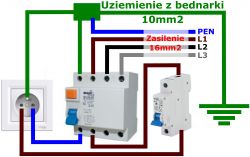
    Connection RCD Issues: Switchgear Testing, PE-N Short-Circuit, Differential Reaction & 3 Phases
    Everything works fine, but I decided to check the differential and something is probably wrong.
    I found a video on the Internet in which it is explained that the differential can be checked by shorting the PE security pin with the neutral N. The differential should work then, but I have no reaction. After pressing the TEST jacking, the differential switches off, but there is no reaction when PE and N are short-circuited.
    The figure shows a fragment of the installation. Of course, all 3 phases are used, but similarly to the one shown in the figure.
    I thought that maybe I would replace the N and PE conductors connected to the differential, i.e. I would attach PE at the bottom, and N at the top.
    It turned out that with such a connection, the differential turns off as soon as I turn something on, and if I try to turn on the differential, e.g. with a lamp connected, it turns off immediately and cannot be turned on at all.
    Is the connection in the drawing correct, or is it with reversed N and PE conductors?
    I have a differential exactly as shown in the attached photo.
  • ADVERTISEMENT
  • Helpful post
    #2 17588334
    Wojtek(KeFir)
    Level 42  
    Shorting N with PE disturbs the sum of the currents flowing through the circuit breaker paths. Well, for it to make sense, ANY electricity must flow. So the circuit must be loaded, even symbolically.
  • ADVERTISEMENT
  • #3 17588337
    malum
    Level 23  
    Wojtek(KeFir) wrote:
    Well, for it to make sense, ANY electricity must flow. So the circuit must be loaded, even symbolically.

    I had an LED lamp connected to the second socket, more precisely three floodlights on a tripod, 20W each.
    Maybe the LEDs themselves are a problem. Maybe it is worth connecting something else?
  • #4 17588404
    radex324
    Level 24  
    malum wrote:
    but there is no reaction at PE and N short circuit.
    Because it will work when the current begins to flow, the N wire is to be connected in advance and the output is down to the socket, and not by any change of wires. If you have it as in the diagram, it should work for you, provided that you make one partition point in the switchgear because PEN after splitting into N and PE cannot be connected anymore.
  • ADVERTISEMENT
  • #5 17589171
    malum
    Level 23  
    radex324 wrote:
    Cause it will work when the electricity starts flowing

    I checked the operation of the differential based on this video: https://www.youtube.com/watch?v=67DG87BCZUM
    In the switchboard, I have 3 sockets connected to one overcurrent switch, and this one to a residual current device. I connected the LED floodlights to one of these three sockets, and I shorted N with PE on the other socket.
    radex324 wrote:
    you will make one division point in the switchboard because PEN after splitting into N and PE

    Behind the residual current circuit breaker I already have a 5x6mm cable and there is no connection between PE and N anywhere.
  • #6 17589706
    kSmuk
    Level 21  
    Appropriate meters are used to measure the RCD disconnection time.
    Shorting PE with N does not make sense, because it will not always turn off the RCD (the leakage current would have to exceed the switch tripping threshold, and the lamps you are writing about do not consume even that much.)
  • #7 17589988
    radex324
    Level 24  
    @kSmuk When connecting a receiver that consumes 0.5A, half of this current will flow through the PE conductor with N PE shorted, which will activate the switch.
  • ADVERTISEMENT
  • #8 17590370
    CYRUS2
    Level 43  
    malum wrote:
    I had an LED lamp connected to the second socket, more precisely three floodlights on a tripod, 20W each.
    Maybe the LEDs themselves are a problem. Maybe it is worth connecting something else?
    Wrong method.

    Methodology of checking the RCD on the outlet.
    15W (or 7W) test tube between the phase and the PE in the socket.
    If the RCD works, you can specify the tripping current in the 2nd check.
    You connect the 8.2k? 2W resistor momentarily between the phase and PE.
    If the RCD works, the RCD threshold current is lower
    from 30mA.

Topic summary

The discussion revolves around issues with a residual current device (RCD) in a switchgear installation. The user reports that while the installation functions correctly, the differential does not respond as expected when shorting the protective earth (PE) with the neutral (N). Responses highlight that shorting PE and N can disrupt current flow, necessitating a load on the circuit for the RCD to function properly. Suggestions include ensuring correct wiring, using appropriate testing methods, and verifying that the load connected (e.g., LED floodlights) is sufficient to trigger the RCD. Various testing methodologies are discussed, emphasizing the importance of using specific resistors and test loads to accurately assess RCD functionality.
Summary generated by the language model.
ADVERTISEMENT