logo elektroda
logo elektroda
X
logo elektroda

Single-Family House Wiring: TN-C Installation, Eaton IS-100/3, OBO BETTERMANN V50-3-280

Goofiq 9042 11
ADVERTISEMENT
Treść została przetłumaczona polish » english Zobacz oryginalną wersję tematu
  • #1 16176293
    Goofiq
    Level 10  
    Hello all,

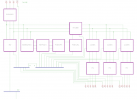
    Please check and comment on the correctness of the wiring diagram that is to be at the entrance to the single-family house. The installation from the ZE is of the TN-C type, there is a 25C fuse behind the meter.
    From the above-mentioned switchgear there are to be protections, meters and a switchboard to 3 further switchboards within this house.

    Legend:
    FR-main, FR1, FR2, FR3 - Eaton IS-100/3 switch disconnectors
    SPD - OBO BETTERMANN V50-3-280
    Fuses - F&F BZ-3
    Controls - F&F L9-3F

    Elements of additional protection against shutdowns I wrote about here
    https://www.elektroda.pl/rtvforum/topic3033679.html

    Gear. nap. - F&F CP-730
    Gear. esp. - F&F PCR-513
    Contactor - F&F ST25-30

    The GSU is below the switchboard.

    Thank you in advance for your help :)
  • ADVERTISEMENT
  • #2 16176305
    opornik7
    Electrician specialist
    The electrician does not ask such questions. A layman should hire an electrician and not do work.
    Sorry, you are not satisfied with my answer. Ask on doctors' forums how to operate on the appendix. You will surely get a satisfactory answer.
  • #3 16176332
    Goofiq
    Level 10  
    I am a bit of an electronics technician by education, more of an IT specialist. I am no stranger to electrics, I have read a lot of topics here and I have learned a lot from them.
    Somehow I do not remember that someone wrote to someone to hire an electrician and there were a few requests to look at the diagram, especially when the SPD was on it.

    Walking on the net and reading a lot of statements on various forums, I am very skeptical of the knowledge of many electricians, who often cannot even connect the grounded ones correctly to the SPD. Often you can see 4-pole switch disconnectors and SPDs in TN-C installation, unprotected phase controls, loading one three-phase RCD for the whole house and other minor faults.
    It is similar with plumbers. I do not want to question anyone's knowledge, but I have a deep understanding of certain topics before I spend the money and do something. Then I start to see what mistakes people make, either out of lack of knowledge, or out of sloppiness, or out of stupid savings, and I come to the conclusion that sometimes I'm afraid to get the first specialist.

    The diagrams are almost sure, it is not complicated, you cannot see any details, e.g. about the diameter of the wires and what, in what order, what to connect to. The only thing I would add is a fire RCD in front of the contactor and between the PE bus and N.
  • #4 16176378
    zbich70
    Level 43  
    Goofiq wrote:
    I am a bit of an electronics technician by education, more of an IT specialist. I am no stranger to electrics, I have read a lot of topics here and I have learned a lot from them.

    Do you know why electrical power engineering and electronics are separate directions in schools and universities? Although they have a little in common and overlap a little. Computer science also overlaps both. Partly.

    No offense, but my friend, the resistor, wrote you well. You won't be a doctor after reading a lot of posts on medical forums ...

    Goofiq wrote:
    The schematics are pretty sure it is not complicated

    This is not an electrical wiring diagram. It is something like a block diagram of an electronic and IT system.
    In the power industry, other information is simplified (e.g. single-line diagram) and other information is exposed.
  • ADVERTISEMENT
  • #5 16176396
    Goofiq
    Level 10  
    zbich70 wrote:
    Do you know why electrical power engineering and electronics are separate directions in schools and universities? Although they have a little in common and overlap a little. Computer science also overlaps both. Partly.

    I'm not saying it coincides, I just wanted to say that I'm not a layman who takes on something he has no idea about.

    zbich70 wrote:
    No offense, but my friend, the resistor, wrote you well. You won't be a doctor after reading a lot of posts on medical forums ...

    I am not going to treat it, but I am no stranger to electrics.

    zbich70 wrote:
    This is not an electrical wiring diagram. It is something like a block diagram of an electronic and IT system.

    Right, it is more of a block diagram, there are no proper electrical symbols there, mainly due to poor knowledge of the Eagle in which it was created. There was also no description of the findings, but I hope that they are obvious.
  • #6 16176556
    rafi84
    Level 24  
    For mine, it's done wrong.
    To find out if it is well designed, you need to know what's next, because at this stage it looks poor. The PEN split point is missing.
    And one more thing, please explain to me how you can be a bit of an electronics technician by education, but more of an IT specialist ?? either you are or you are not ;)
    It's like "I'm not a gynecologist, but I can look"
  • #7 16176632
    kozi966
    Moderator of Electricians group
    Goofiq wrote:
    Please check and comment on the correctness of the wiring diagram that is to be at the entrance to the single-family house. The installation from the ZE is of the TN-C type, there is a 25C fuse behind the meter.

    Unfortunately, this diagram is hard to read.
    FR at the "entrance" is ok.
    The PEN bus (and not the PE in a colleague's accident) is not grounded by the GSW (theoretically by the apparatus - protector but it cannot be).
    I don't understand the fuse-indicator-relay system. How is it supposed to work?
    It is connected in series?
    What does the contactor do in this system?
    Why does a friend have 3 additional counters?
    Where are the installation security?
    No information on cable cross-sections, security calculations.

    A little more description, please ...
    This is an example electrical diagram (partial):
    Single-Family House Wiring: TN-C Installation, Eaton IS-100/3, OBO BETTERMANN V50-3-280
  • #8 16176771
    CYRUS2
    Level 43  
    Goofiq wrote:
    I am not going to treat it, but I am no stranger to electrics.
    IIe electronic devices have you designed and made?
  • ADVERTISEMENT
  • #9 16177358
    Goofiq
    Level 10  
    zbich70 wrote:
    Do you know why electrical power engineering and electronics are separate directions in schools and universities? Although they have a little in common and overlap a little. Computer science also overlaps both. Partly.

    Specializations? I will not be an energy specialist. You can do SEP grade "E" permits which you can legally put switchboards. Getting such permission is not a big deal. Recently, someone in my family has been doing them and he has no problem with it and is a builder by education and often calls me for advice.
    I will not try to measure the insulation resistance and grounding because I am aware of the lack of knowledge, and even less of the measuring equipment.

    rafi84 wrote:
    To find out if it is well designed, you need to know what's next, because at this stage it looks poor.

    Next there are to be switchgears with protection for home appliances, RCDs rather single-phase and ES.

    rafi84 wrote:
    The PEN split point is missing.

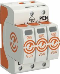
    The OBO BETTERMANN V50-3-280 has two outputs. One for direct connection to ground, the other for the PEN bus. I like this solution, the valued DEHN also has it. Often, the protectors are connected via the PEN bus and this is not good, in the event of activation, the load passes through additional elements and so goes straight to the GSU.
    Single-Family House Wiring: TN-C Installation, Eaton IS-100/3, OBO BETTERMANN V50-3-280

    rafi84 wrote:
    And one more thing, please explain to me how you can be a bit of an electronics technician by education, but more of an IT specialist ?? either you are or you are not ;)
    It's like "I'm not a gynecologist, but I can look"

    Electronic technical school and later IT studies and currently working as an IT specialist. Electronics is a hobby, mainly Arduino, Raspberry Pi.


    kozi966 wrote:
    The PEN bus (and not the PE in a colleague's accident) is not grounded by the GSW (theoretically by the apparatus - protector but it cannot be).

    So, despite the fact that the protector has a second output, go down separately to the GWS (GSU?)

    kozi966 wrote:
    I don't understand the fuse-indicator-relay system. How is it supposed to work?

    I am in a hurry to explain.
    I once described the situation in this topic https://www.elektroda.pl/rtvforum/topic3033679.html but I will repeat here. It happens that during some work in the distribution they turn off the electricity, sometimes they turn it on for short intervals, sometimes they turn on and off for two or three seconds within one second. Once upon a time something like this happened and I noticed, I thought it was probably one time. But no, it was the same recently. I am writing about a situation that I noticed while at home and how many times it could have happened when I was away from home.

    The security consists of the following elements:
    Gear. nap. - F&F CP-730
    Voltage relay that disconnects the current when the supply voltage is too low or too high

    Gear. esp. - F&F PCR-513
    Time delay relay that will disconnect in the event of power failure and turn on with a set delay when the voltage recovers.

    Contactor - F&F ST25-30
    Contactor as an actuating device

    Dodawkowo
    Fuses - F&F BZ-3
    Fuses, which were to protect only the controls, but there is no problem to protect the controls and the above systems.

    kozi966 wrote:
    It is connected in series?

    Sorry, it's actually not very bright in places, especially the controls that appear to be connected in series :)

    kozi966 wrote:
    What does the contactor do in this system?

    jw

    kozi966 wrote:
    Why does a friend have 3 additional counters?

    These are outputs to further local switchboards with final fuses for socket and lighting circuits

    kozi966 wrote:
    Where are the installation security?

    It seems to me that a selective RCD 0.3A should be included here in the role of fire protection. I did not want to add any ES due to the fact that they are in further switchboards. There is a main fuse from ZE 32C. Throwing in additional fuses here can be problematic. When their performance characteristics match, this can create additional problems such as instead of throwing out one fuse that protects the end circuit, it will throw out the one inside, disconnect more circuits, and you will have to walk and turn on more.

    kozi966 wrote:
    No information on cable cross-sections, security calculations.

    4x10 comes to the switchboard. For connections, I intend to use fi 10 cables with sleeves and, where possible, rails connecting the contacts of the equipment.

    kozi966 wrote:
    A little more description, please ...

    It seems to me that I have already described everything above :)

    kozi966 wrote:
    This is an example electrical diagram (partial):

    Thanks for the example. I am not so familiar with eagle, I suggested a lot of flowcharts posted here and made one.

    kozi966 wrote:
    Have you designed and manufactured electronic devices?

    It is difficult to answer this question because I am not professionally involved in it. As a hobby, I had more fun with it in the Technical School, now it's more between electronics and computer science, more like Arduino etc. but it's something completely different than here. In practice, I had some contact with home switchgears and connections of air conditioning devices when I was helping someone with assembly. Plus, I have a built-in curiosity to analyze and learn about these kinds of things when I have
    such a need.
    This is some kind of exam, do you want to prove to me that I really don't know anything and I don't do itI know? If this type of knowledge was binary, then suddenly there would be much less experts in many fields. More than once I met people who were super specialists in various fields in talking and on paper, and when it came to what it was, something else came out. I'm not going to belittle people who are really good and unbendable here. Fortunately, there are also such and I prefer to deal with them because I can only take advantage of it. Why did I prefer to come in here and ask than just do something and get the opinion of others somewhere :)
  • #10 16177493
    kozi966
    Moderator of Electricians group
    Goofiq wrote:
    So, despite the fact that the protector has a second output, go down separately to the GWS (GSU?)

    Of course.
    Goofiq wrote:
    Throwing in additional fuses here can be problematic.

    I was only interested in the tab. load. If they are, it's ok.
    Goofiq wrote:
    For connections, I intend to use fi 10 cables with sleeves and, where possible, rails connecting the contacts of the equipment.

    okay.
    Goofiq wrote:

    kozi966 wrote:
    Have you designed and manufactured electronic devices?

    I didn't write it.
  • ADVERTISEMENT
  • #11 16178028
    CYRUS2
    Level 43  
    Goofiq wrote:
    You can do SEP grade "E" permits which you can legally put switchboards. Getting such permission is not a big deal.
    That's how people value the knowledge of electricians.
    Why bother with the rights of an electrical designer?
    Cyrus2 wrote:
    Have you designed and manufactured electronic devices?
    That was my question.
    Quote:
    As a hobby, I had more fun with it in the Technical College
    Thank you for your answer.
  • #12 16179117
    Topolski Mirosław
    Moderator of Electrical engineering
    Goofiq wrote:
    You can do SEP grade "E" permits which you can legally put switchboards. Getting such permission is not a big deal. Recently, someone in my family has been doing them and he has no problem with it and is a builder by education and often calls me for advice.

    It is just like with a driving license. Many people get them only because of the lack of knowledge and practice, they are most often the perpetrators of tragedies on the road. he should give you advice - but he's only a construction worker who thinks he's an electrician.

Topic summary

The discussion revolves around the correctness of a wiring diagram for a TN-C installation at the entrance of a single-family house. The user seeks feedback on the diagram, which includes components such as Eaton IS-100/3 switch disconnectors, OBO BETTERMANN V50-3-280 surge protective devices (SPDs), and various fuses and controls. Responses highlight concerns about the diagram's clarity, the absence of critical elements like the PEN split point, and the need for proper electrical symbols. Some participants express skepticism about the qualifications of electricians and emphasize the importance of accurate design and installation practices in electrical engineering.
Summary generated by the language model.
ADVERTISEMENT