logo elektroda
logo elektroda
X
logo elektroda

Beginner's Electrical Switchgear Diagram for Single-Family House: YKY5x16, TN-S System, RCDs

viruz997 11520 19
ADVERTISEMENT
Treść została przetłumaczona polish » english Zobacz oryginalną wersję tematu
  • #1 16449409
    viruz997
    Level 16  
    As a beginner, I'd like to make sure I have drawn the electrical switchgear diagram correctly. The switchgear is intended for a single-family house. There is 35mb from the measuring connector to the switchboard - YKY5x16 - TN-S network system.
    Is the switchboard well designed, what should be changed?
    Is the use of additional-separate residual current devices for laundry / kitchen / bathroom circuits necessary? In the event that the switch trips, I am able to diagnose overcurrent switches where the leakage current is.
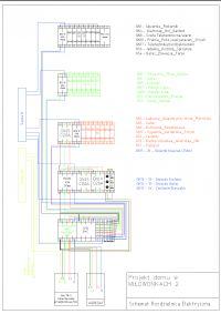
    Beginner's Electrical Switchgear Diagram for Single-Family House: YKY5x16, TN-S System, RCDs
  • ADVERTISEMENT
  • #2 16449450
    zbich70
    Level 43  
    viruz997 wrote:
    electrical switchgear scheme. Switchgear designed for
    Is it a switchgear or a switchgear after all?
    viruz997 wrote:
    did I draw the diagram of the electrical switchboard correctly?
    Colleague "designer" heard about single-line diagrams?
    viruz997 wrote:
    In the event that the switch trips, I am able to diagnose overcurrent switches where the leakage current is.

    Please enter how you will diagnose it.
  • #3 16449521
    viruz997
    Level 16  
    zbich70 wrote:
    Is it a switchgear or a switchgear after all?


    Editing posts in this specific forum requires the approval of a moderator so by then your colleague will have to look at these two names, later I will change to a switchboard.

    zbich70 wrote:
    Colleague "designer" heard about single-line diagrams?


    Please indicate the place where I wrote that I am a designer? The word designed does not mean that you are a designer!
    Yes, I have heard about single-line, but the posted multi-line diagram (which is perhaps less readable) shows exactly the same so I do not understand where the problem is.

    As for residual current devices in one case, the situation may be as follows:
    The earth leakage circuit breaker has tripped - I turn off all off overcurrent - I turn on the RCD - turn on the circuit breakers responsible for individual circuits in turn - then find the faulty device.
  • ADVERTISEMENT
  • #4 16449559
    zbich70
    Level 43  
    viruz997 wrote:

    As for residual current devices, in one case the situation may be as follows

    It's good that a colleague wrote in one case .
    And what about the others?

    Example. Doziaia N. What are you doing? Do you still have eski?
  • ADVERTISEMENT
  • #6 16449691
    opornik7
    Electrician specialist
    Installation 100% so made will not be technically efficient and will not work. Too many cardinal errors.
  • #7 16449733
    Anonymous
    Anonymous  
  • #8 16449859
    mawerix123
    Level 39  
    viruz997 wrote:
    TN-S network layout


    For sure :?: Not TN-C with a chapter on TN-CS :?:
  • ADVERTISEMENT
  • #9 16449917
    opornik7
    Electrician specialist
    viruz997 wrote:
    From the measuring connector to the switchboard at home there is 35mb - YKY5x16 - TN-S network system.

    mawerix123 wrote:
    For sure :?: Not TN-C with a chapter on TN-CS :?:

    :?: :?:
  • #10 16449944
    mawerix123
    Level 39  
    opornik7 wrote:
    viruz997 wrote:
    From the measuring connector to the switchboard at home there is 35mb - YKY5x16 - TN-S network system.

    mawerix123 wrote:
    For sure :?: Not TN-C with a chapter on TN-CS :?:

    :?: :?:


    There may be 5x16 from the connector and there is probably a classically incorrect PEN separation in it, but this does not create a power supply for the house in the TN-S network .... And as for the connector comes 5x cable to the recipients .... about TN-S :?:
  • #11 16450125
    kortyleski
    Level 43  
    Diagram as much as possible could be read wrong. With RCD you will be able to bet which and when will disconnect.
  • #12 16450312
    kozi966
    Moderator of Electricians group
    kortyleski wrote:
    With RCD you will be able to bet which and when will disconnect.

    First of all, none of them will want to join.
  • #13 16450361
    retrofood
    VIP Meritorious for electroda.pl
    viruz997 wrote:
    As for residual current devices in one case, the situation may be as follows:
    The earth leakage circuit breaker has tripped - I turn off all off overcurrent - I turn on the RCD - turn on the circuit breakers responsible for individual circuits in turn - then find the faulty device.

    I guarantee you that switching on any redundant protection will cause an RCD reaction. I wonder how you will then determine the faulty receiver and its location.
  • #14 16456520
    viruz997
    Level 16  
    The diagram sent was not legible and it was mainly about the arrangement of the apparatus and then the selection of the size of the switchgear.
    Four leads are connected to the measuring connector and the PEN is separated there. As I mentioned, a 5x16 cable goes to the switchgear in the house. The idea for the drawing of the diagram was born at the time of the proposal of 2 electrical companies invited (read 1 max 3 3f residual current switches, then two overcurrent switches for lighting ground floor / first floor, and several for 230V sockets, 1 overcurrent switch 3f, switch aggregate network - that's all Of course without no documentation after the implementation. I am not saying that it was badly planned by them, but once in school I remember it a little differently everything was presented and watching the newly made installations a little different from the proposals of the above mentioned professionals. Using the links given above as far as my reasoning has improved my diagram I am asking for further tips .... I am adamant in pursuing my goal :)
  • #15 16456566
    elpapiotr
    Electrician specialist
    Hello.

    Your inflexibility is admirable, but when RCD number 1 works, I can see the darkness in the whole house. Probably because the rest of the diagram was not shown.

    PS. Why a 2.5 mm? wire for the lighting circuit?
  • #16 16456625
    viruz997
    Level 16  
    So you will be so kind and tell us where the problem lies in the diagram and show its solution? Because I have already lost ideas (rcd connection - Phase and N from the main bus, second pair of terminals - N from the circuits, phase through the overcurrent?) Or maybe it is about socket and lighting circuits on one rcd switch? Or maybe wrong symbols at lighting circuits. The lighting cable is 1.5 - a printing error.
  • #17 16456686
    elpapiotr
    Electrician specialist
    Hello.
    I kindly suggest and advise that only some lighting circuits require the use of RCDs, together with circuit breakers.
  • #18 16456713
    viruz997
    Level 16  
    If you reason well you are talking about lighting circuits for the bathroom, lighting on the facade / garden, laundry. And the other lighting circuits only with overcurrent switches ..
  • #19 16456840
    Łukasz-O
    Admin of electroenergetics
    Apart from other issues, completely incorrect circuit layout.
    That much is written on the forum about separate circuits for devices above 2kW, and here on the diagram one big mix.
  • #20 16457041
    opornik7
    Electrician specialist
    Lighting and sockets on one RCD - error. Darkness will come after it has acted. Paweł wrote about it in post # 15.
    What fungus protects the stops?
    Why T2 Enough? How is the building powered?
    viruz997 wrote:
    Four leads are connected to the measuring connector and the PEN is separated there. As I mentioned, a 5x16 cable goes to the switchgear in the house.

    Nonsense that professionals fight. As you can see without success.
    You don't write anything at all about protection from paralysis. What about GSU? What about expansion joints? What about earth electrode?
    Łukasz-O wrote:
    Apart from other issues, completely incorrect circuit layout.
    That much is written on the forum about separate circuits for devices above 2kW, and here on the diagram one big mix.

    We write, we write and home contractors do not know what we are writing about :D
    Buddy viruz997, read with understanding what we wrote. Compare this with the norms and other legal acts and return with ....... the correct installation scheme.

Topic summary

The discussion revolves around the design and correctness of an electrical switchgear diagram for a single-family house, specifically using a YKY5x16 cable in a TN-S system. Participants critique the diagram's clarity and technical accuracy, highlighting issues such as incorrect circuit layouts, the necessity of separate residual current devices (RCDs) for specific circuits (like laundry, kitchen, and bathroom), and the importance of proper PEN separation. Concerns are raised about the potential for tripping RCDs affecting multiple circuits and the need for distinct circuits for high-power devices. The conversation emphasizes the importance of adhering to electrical standards and best practices in residential installations.
Summary generated by the language model.
ADVERTISEMENT