logo elektroda
logo elektroda
X
logo elektroda

Understanding Capacitor Markings in Old Tube Radio Restoration - Decipher Their Values

FireEnd 5925 11
ADVERTISEMENT
Treść została przetłumaczona polish » english Zobacz oryginalną wersję tematu
  • #1 16200015
    FireEnd
    Level 11  
    Hello.
    I started overhauling my old tube radio.
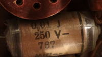
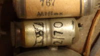
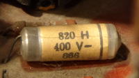
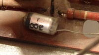
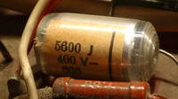
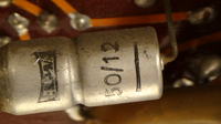
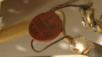
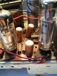
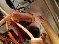
    The first step after cleaning the top layer of dust, the first thing I want to do is replace all the capacitors. However, there was a problem with their markings. Below I paste photos of capacitors that I have doubts about.
    Please explain these signs and how to read them in the future.
    Understanding Capacitor Markings in Old Tube Radio Restoration - Decipher Their Values Understanding Capacitor Markings in Old Tube Radio Restoration - Decipher Their Values Understanding Capacitor Markings in Old Tube Radio Restoration - Decipher Their Values Understanding Capacitor Markings in Old Tube Radio Restoration - Decipher Their Values Understanding Capacitor Markings in Old Tube Radio Restoration - Decipher Their Values Understanding Capacitor Markings in Old Tube Radio Restoration - Decipher Their Values Understanding Capacitor Markings in Old Tube Radio Restoration - Decipher Their Values Understanding Capacitor Markings in Old Tube Radio Restoration - Decipher Their Values
  • ADVERTISEMENT
  • #2 16200088
    Piotr2608

    Level 41  
    As well I remember, if not someone to correct me:
    200i - 20pF 1600V
    0.01J - 1nF 250V
    820H - 82pF 2.5% tolerance
    200J - 20pF 5% tolerance
    5600J - 560pF 5% tolerance
    50/12 - ???
    3300 - 330pF 1600V
  • ADVERTISEMENT
  • #4 16200104
    abart64
    Level 33  
    I guess the old ones were marked directly. 200 is 200p, 820 is 820p.
    I do not associate any with the designation, for example 331.
    50/12 is 50u 12V
  • ADVERTISEMENT
  • #5 16200152
    _jta_
    Electronics specialist
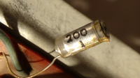
    767 Miflex in the third photo - unfortunately only the climatic category is visible. 2/70 - 2uF / 70V electrolyte. The letter H or J is accuracy - this is in the second link in # 3.

    I think, however, that the markings contain capacitances in uF (0.01 = 10nF), or in pF - that's what I read, according to this I took into systems and these systems worked as predicted. The fashion for marking, where the last digit gives the power of 10, used to only apply to barcodes of resistors, and moved to capacitors when they were SMD.
  • #6 16200238
    zetdeel
    Level 39  
    From what you've shown, there are only two "electrolytes" to replace: 50uF / 15V and 2uF / 70V. The others are styroflex capacitors, characterized by picofarads. If they are operational - do not move! This also applies to the ceramic "lollipop" 3300pf / 500V.
  • #7 16200632
    FireEnd
    Level 11  
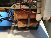
    Even in 55-year-old equipment, do not touch the styroflexes? Maybe they will last a few more years, but the paper ones need to be replaced? Understanding Capacitor Markings in Old Tube Radio Restoration - Decipher Their Values Understanding Capacitor Markings in Old Tube Radio Restoration - Decipher Their Values
  • ADVERTISEMENT
  • #8 16200677
    398216 Usunięty
    Level 43  
    FireEnd wrote:
    Even in 55-year-old equipment, do not touch the styroflexes? Maybe they will last a few more years,
    They will outlive us all for sure.
    FireEnd wrote:
    must the paper ones need to be replaced?
    These "potatoes" must be replaced immediately.
  • #9 16202078
    _jta_
    Electronics specialist
    The paper ones have a dielectric made of oil-saturated paper - and at least for a while it was oil that evaporated after a long time (decades) if the capacitor was not tightly closed - and this reduced the capacitance of the capacitor and could also lower the breakdown voltage. This paper is brown in color, similar to typical kraft paper. Once, someone from my extended family showed me the "Wisła" TV set - one of the first Polish TV sets - still functional, but after replacing the paper capacitors.
  • #10 16204812
    FireEnd
    Level 11  
    Well, I am replacing the potatoes, but ... Can anyone tell me what's going on with those with three leads? Understanding Capacitor Markings in Old Tube Radio Restoration - Decipher Their Values
    Was it shielding? If so, how do you check which derivation is which?
  • #11 16205088
    398216 Usunięty
    Level 43  
    Picture not very clear ...
    The mass was not marked as far as I know. There is a black strip on the casing - it means an electrode connected to the outer lining - which (in some cases is important) as a screen.
    Check with a meter that there is no connection between these wires on one side.
    And by the way - what is this equipment? And what is the marking of this capacitor?
  • #12 16205477
    FireEnd
    Level 11  
    In the diagram it looked like shielding, and indeed one lead of the capacitor was connected to ground. Dismantling the capacitor revealed that it was a piece of aluminum foil shielding the capacitor. I put on wims, ignoring the shielding. In case of increased interference, I will do some research. The capacitor was 22nF 400V.
    The receiver is a diora sonata 22002.

Topic summary

The discussion revolves around understanding capacitor markings in old tube radios during restoration. Participants provide insights on how to interpret various capacitor values, including examples of common markings such as 200i (20pF 1600V), 0.01J (1nF 250V), and 50/12 (50uF 12V). It is noted that styroflex capacitors, often marked in picofarads, should generally be left untouched if operational, while paper capacitors are recommended for replacement due to potential degradation over time. A specific case involving a capacitor with three leads is discussed, revealing it was used for shielding, with one lead connected to ground. The equipment in question is identified as a Diora Sonata 22002.
Summary generated by the language model.
ADVERTISEMENT