logo elektroda
logo elektroda
X
logo elektroda

Siemens S7-300 Profibus: Configuring 6SL3525-0PE17-5AA1 Power Modules & 6SL3544-0FB20-1PA Modules

and_rog 5763 8
ADVERTISEMENT
Treść została przetłumaczona polish » english Zobacz oryginalną wersję tematu
  • #1 16207491
    and_rog
    Level 23  
    Hello. I basically have 2 sets of questions, so in order:

    1.
    I have an S7-300, a Profibus network is built on this processor. There are power modules in the Profibus network (6SL3525-0PE17-5AA1) and on them communication modules 6SL3544-0FB20-1PA). And here are the questions:
    Is Step 7 v5.5 or Step 7 Professional 2010 enough to configure Profibus as above (they differ in something important?) If not, what program do I need? Is this what the "SINAMICS MICROMASTER STARTER" is for?
    If the 6SL3544-0FB20-1PA module breaks, there is a memory card in (each) modules, is it enough to put it into the new module and replace the module to restart the machine?

    2.
    I also have the S7-1200 and the TIA Portal v13 Basics.
    Can I build a Profinet network based on Ethernet on the S7-1200 controller? I was looking for an option to add a device (e.g. G120 Siemens drive) in TIA Portal Basics, but it is not. If such a network can be built, what program do I need? TIA Portal Professional?
    What is the cheapest device that can be used to build such a network - I mean something (e.g. an inverter, but the inverter is not cheap), as long as there is data exchange, with an ethernet port (such a network just for learning).

    Thank you for reading this post patiently. If someone decides to write a reply - thanks a lot.

    Best regards!
  • ADVERTISEMENT
  • #2 16211060
    mateuszmk901
    Level 11  
    Regarding question 1:


    As far as I know, the step 7 v5.5 version is the latest. And with its help, you are able to configure the PLC (including the profibus network, more precisely in HvConfig).
    In fact, that's all you need.
    "SINAMICS MICROMASTER STARTER" / here, as the name suggests, soft for configuring micromaster inverters
  • Helpful post
    #3 16211132
    kornik280
    Level 18  
    Question 2:
    You can build a profinet network on the basis of the S7-1200, if you want to use an external device to build the network, you need to import the gsdml file for this device.
    If you want to build the cheapest profinet network, the easiest and cheapest way is to use two controllers.
  • ADVERTISEMENT
  • #4 16213738
    and_rog
    Level 23  
    A good idea. I have 2 S7-1200. But now how to combine these two programs into one project? I gave export on the tags, then import in the second project, and I have it, but it doesn't work like that anymore.
    .... ok, merged projects.
  • ADVERTISEMENT
  • #6 16222519
    and_rog
    Level 23  
    Interesting facts: the S7-1200 can hang so beautifully that everything is checked: all registered data (retain and not retain), states in the program, etc; Diagnostic buffer below (reason): "Serious firmware exception". Cool thing.
    Siemens S7-300 Profibus: Configuring 6SL3525-0PE17-5AA1 Power Modules & 6SL3544-0FB20-1PA Modules

    But to the point:
    Two programs merged into one project, network configuration created (I do not know if the name S7_connection_1 should appear twice)
    Siemens S7-300 Profibus: Configuring 6SL3525-0PE17-5AA1 Power Modules & 6SL3544-0FB20-1PA Modules

    Connection parameter: entered what you need (I think):
    Siemens S7-300 Profibus: Configuring 6SL3525-0PE17-5AA1 Power Modules & 6SL3544-0FB20-1PA Modules

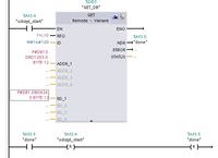
    But the GET instruction doesn't take parameters, I have them in red:
    Siemens S7-300 Profibus: Configuring 6SL3525-0PE17-5AA1 Power Modules & 6SL3544-0FB20-1PA Modules

    I use help or instructions from the net, e.g.
    https://cache.industry.siemens.com/dl/files/6...tt_108741/v1/put_get_sequencer_s7-1200_en.pdf

    But I'm missing something ... Someone will tell me how to correctly address, for example, reading 3 variables from the address from Procek "DATA" .ND [0] to PLC_2 "S" .Real [0]? Or where to read it?
  • Helpful post
    #7 16222692
    Markos80

    Automation specialist
    See the built-in help and see how to enter pointers (Example: P # DB10.DBX5.0 Byte 10). Convert DBD to DBX.
    PS: GET / PUT is not Profinet communication in the strict sense :) If you want, from firmware 4.0 you can use 1200 as an I-Device (Profinet I / O). In the Profinet port configuration, you need to select IO device and sign it to the second controller. Then select the areas to be replaced in the table.
  • ADVERTISEMENT
  • #8 16223425
    kornik280
    Level 18  
    I will add from myself:
    The DB block cannot be "Optimized block access", and in the CPU properties "Protection-> Connection mechanism" you must select "Permit access with PUT / GET"
  • #9 16224450
    and_rog
    Level 23  
    Markos' advice helped - DBX computer took over instead of DBD. I don't have "Optimized block access" anywhere, and now I can't find it, but I think I have GET / PUT checked. It is different after making the changes:
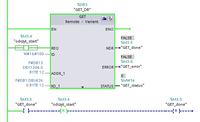
    Siemens S7-300 Profibus: Configuring 6SL3525-0PE17-5AA1 Power Modules & 6SL3544-0FB20-1PA Modules
    the GET instruction executes all the time - ie after its initialization, it is still green (active), but there is neither done, error, nor data transmission itself. Where is it coming from? One processor on firmware 3, and the other 4 - is this a problem? In the processor settings I also have :P artner port: Any partner. It can be like that? Although it must, in principle, because I can choose a second processor (i.e. the appropriate Procek or PLC_2), but then I cannot give "OK" because it is inactive.

    January 27, 2017:
    Anyone have a working program that they can post, with GET and / or TM_Mail instructions? I combine and combine and nothing ... When creating an instruction, it says that it creates a DB table for this instruction, but I can't find this table anywhere. Where is it made? Can you see her?

    January 28, 2017:
    On the forums I read that the "Error" status and error description occur only for one scan of the program, so you need to make traps in the program to register them. After making this change: however, there is an error, with status "1", that is:
    Siemens S7-300 Profibus: Configuring 6SL3525-0PE17-5AA1 Power Modules & 6SL3544-0FB20-1PA Modules
    Everything seems to work, but I forgot about something .... The IP network is working for sure, cables, etc., are working. After my experiments, the Diagnostic Bufer looks like this:
    Siemens S7-300 Profibus: Configuring 6SL3525-0PE17-5AA1 Power Modules & 6SL3544-0FB20-1PA Modules

    I don't know what to check if the configuration below is correct?
    Siemens S7-300 Profibus: Configuring 6SL3525-0PE17-5AA1 Power Modules & 6SL3544-0FB20-1PA Modules

    Now I found out that if the read / write areas are identical (e.g. 4 bytes), it is an error and the status "1", and if the areas are incorrectly given (different length), it is error 10: Access to the local user memory not possible (for example, access to a deleted DB).

    It worked. But there was a fight. So I close the topic ...

Topic summary

The discussion revolves around configuring Siemens S7-300 and S7-1200 PLCs within Profibus and Profinet networks. For the S7-300, users confirm that Step 7 v5.5 is sufficient for configuring the Profibus network, specifically using HvConfig. The "SINAMICS MICROMASTER STARTER" software is intended for configuring Micromaster inverters. Regarding module replacement, transferring the memory card from a faulty 6SL3544-0FB20-1PA module to a new one is suggested as a method to restart the machine. For the S7-1200, it is possible to build a Profinet network using TIA Portal, but users need to import the GSDML file for external devices. Issues with merging projects and communication between controllers using GET/PUT instructions are also discussed, highlighting the importance of proper configuration settings and firmware compatibility.
Summary generated by the language model.
ADVERTISEMENT