logo elektroda
logo elektroda
X
logo elektroda

Samsung UE32ES6100 TV - Replacing Short-Circuited Edge Lighting Diodes, SLC5012M Control

Piko 14706 19
ADVERTISEMENT
Treść została przetłumaczona polish » english Zobacz oryginalną wersję tematu
  • #1 16217266
    Piko
    Level 22  
    Hello.
    I have a tv with broken edge lighting. About a week ago I got tired of replacing 9 diodes that went short-circuited in one of four branches of 11 pcs.
    Massacre. Somehow I exchanged glad I turned and gave back. A few days, the telephone and TV returned back, this time there are 10 diodes in the other half in the same branch.
    Can you see something does not require control?
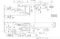
    Now yes? The control is made on SLC5012M which is nice described in the post about the same series but with a larger diagonal. [url=] https://elektroda.pl/rtvforum/topic3178142.html [/url]
    I will watch him. For now, the initial inspection and measurements have completely failed. Full symmetry. I will solder the diodes tomorrow and measure the voltage.
    However, I am interested in another matter. What is the quickest to pick in such a case, R, L, C, transistors or scalac? You can't see cold solder, cracks, bulges ...
    I am asking people with more experience in this direction for any hints.
    Thank you and best regards, Piko.
  • ADVERTISEMENT
  • #2 16218231
    buli1
    Level 25  
    Have you checked the other LEDs? Have you just replaced the burned and that's all?
  • ADVERTISEMENT
  • #3 16218476
    Piko
    Level 22  
    buli1 wrote:
    Have you checked the other LEDs ?? or just replaced the burned and that's all ...


    Hello. And what does a colleague understand by checking the other diodes? To eliminate the damaged one has to check each one individually and then in a row if there are no differences in lighting? Before I folded the matrix, the TV came for a while without catching any irregularities? It was OK.
    I just ask why most often is caused by some drastic voltage surge or lack of control of the current flowing through the diodes?
    And here I have my theory but I do not know if it is true?
    There are 44 diodes, 11 in a row, and two rows are connected in parallel and come from one half and the other 2x11 pcs. from the other half of the controller. It is, for example, assuming that one of the diodes in any branch increases its resistance or simply "goes into a break". It extinguishes the entire branch of 11 pcs and reduces the controlled current of the controller and the one from the "office" raises the supply voltage to such a value to achieve satisfactory current (of course, for 22 items and there are only 11 items)?
    And in this way electronics can be faultless and the problem is only in diodes. That's all my theory. Am I right?

    Thanks for the reply and best regards.
  • #4 16218567
    mirex
    Level 43  
    Piko wrote:
    There are 44 diodes, 11 in a row, and two rows are connected in parallel and come from one half and the other 2x11 pcs. from the other half of the controller. It is, for example, assuming that one of the diodes in any branch increases its resistance or simply "goes into a break". It extinguishes the entire branch of 11 pcs and reduces the controlled current of the controller and the one from the "office" raises the supply voltage to such a value to achieve satisfactory current (of course, for 22 items and there are only 11 items)?
    ...Am I right?

    You do not have. How can you force the current to flow when the diode has a break?
    But warm, even with slightly increased branch resistance. Keep trying.
    and one more thing ... LED drivers have both current and maximum voltage control.
    And to the question asked - diodes, SLC5012M, or application components - there can be no definite answer. If only because you assume that this momentary phenomenon causes a fault. Probably temporary, because we know nothing. You have finished watching the glow, which is a very "false" measurement. There is nothing about currents and voltages.
    Buy a complete backlight, replace SLC5012M for peace of mind, re-diagnose.
  • #5 16218651
    Piko
    Level 22  
    mirex wrote:

    You do not have. How can you force the current to flow when the diode has a break?
    But warm, even with slightly increased branch resistance. Keep trying.


    And here we probably don't understand each other. I mentioned that these 44 diodes are connected in 4 series of 11 diodes. If they were all in line I would agree with you. And here the series consists of 11 diodes and two identical branches are connected to the controller. Since one, let's call it conventionally, the current dropped by half, so the controller raises the voltage to reach the expected current value. And here lime, can't do it? I see it this way.

    So far, I have only measured voltage drops on diodes because I did not know what to buy? 7032 3V diodes. Tomorrow the courier will bring a new set of LEDs. And I will exchange it tonight because I still have 15 bought. Then I will check the electricity? I approached the first repair without any special commitment but with great care and diligence not to spoil something worse.
    Now, in order not to remove the matrix every now and then I prefer to look more closely.
    Thanks and for that good word. Regards Piko.
  • #6 16218868
    mirex
    Level 43  
    Piko wrote:
    And here we probably don't understand each other. I mentioned that these 44 diodes are connected in 4 series of 11 diodes. If they were all in line I would agree with you. And here the series consists of 11 diodes and two identical branches are connected to the controller. Since one, let's call it conventionally, the current dropped by half, so the controller raises the voltage to reach the expected current value. And here lime, can't do it? I see it this way.

    You don't see well. Look how this LED power supply is built!
    Piko wrote:
    So far, I have only measured voltage drops on diodes because I did not know what to buy?

    Really? And I thought everything was written on the power supply ?!
    Well, we don't even know what power supply you have. ;)
    And I have to quote two things:
    Piko wrote:
    There are 44 diodes, 11 in a row, and two rows are connected in parallel and come from one half and the other 2x11 pcs. from the other half of the controller.
    Piko wrote:

    And here we probably don't understand each other. I mentioned that these 44 diodes are connected in 4 series of 11 diodes. If they were all in line I would agree with you. And here the series consists of 11 diodes and two identical branches are connected to the controller.

    How many diodes form a series from the power input to the control key?
    Since the branches are equal, they are powered from the same inverter, I remind you again that the power supply has overvoltage protection. Calculated accordingly. So how are your suggestions about excessive voltage increase?
    (Only that this is a theory, because Samsung designs are for ... Both in terms of current and voltage are bottom. Measure the operating voltage of the LED driver when the backlight is unplugged, you will understand.) ;)
  • #7 16219143
    Piko
    Level 22  
    mirex wrote:
    Really? And I thought everything was written on the power supply ?!
    Well, we don't even know what power supply you have. ;)

    How many diodes form a series from the power input to the control key?
    Since the branches are equal, they are powered from the same inverter, I remind you again that the power supply has overvoltage protection. Calculated accordingly. So how are your suggestions about excessive voltage increase?
    (Only that this is a theory, because Samsung designs are for ... Both in terms of current and voltage are bottom. Measure the operating voltage of the LED driver when the backlight is unplugged, you will understand.) ;)


    I will answer this question because I can do so much now. Is it written on the power supply I did not notice. The symbol is BN44-00517A. And I just measured the voltage on the capacitors what comes out of the diodes .. (of course without load) 44V appears for a while and after about 1 second. increases to 128 and so sways 118-128..V Both in one channel and the other.
    Is this not enough to burn the most powerful LEDs? How do you understand this? ;)

    And as for the number of diodes in a row I have written many times that there are 11.

    Once again, best regards, Piko.
  • #8 16219413
    mirex
    Level 43  
    mirex wrote:

    How many diodes form a series from the power input to the control key?
    Piko wrote:
    And as for the number of diodes in a row I have written many times that there are 11.

    Draw a real system and think about it. Because the discussion ceases to make sense.
    Piko wrote:
    And I just measured the voltage on the capacitors what comes out of the diodes .. (of course without load) 44V appears for a while and after about 1 second. increases to 128 and so sways 118-128..V Both in one channel and the other.

    Then think about what the first tension is and where the second tension comes from.
    Piko wrote:
    Is this not enough to burn the most powerful LEDs? How do you understand this?

    I understand it exactly how it works. You not yet. But we're close. ;)
    No, it's not enough to damage the diodes. If only because they are not connected at all. :)
    There can be 200V. ;) And still nothing has to happen, even if they were connected. :)
    Think calmly why I wrote so and what is the task of causing that the diodes will not receive more than they should. ;) Of course, theoretically considering and assuming that everything is in working order. ;)
    When you start it, you can see exactly what elements are involved in lighting the diodes, then take an oscilloscope to see for yourself how it works.
  • #9 16220136
    lisek
    Service technician RTV
    I wrote this in one of the topics
    Quote:
    remember LEDs have a production spread of Uf = 3.1-3.7V

    - I doubt that when installing garland_linijek or string selected LEDs in this respect
    On the tape they go like it goes ...


    Give me what matrix.
    Enter which power supply.

    __________________

    Tem 3D model from 2012 frequented on pcb: BN41-01812A
    - then, depending on the solder's wealth, it was called> e.g. BN94-06045B / / BN94-05678M / BN94-05920B

    LTJ320HW04-J / or Slovakia was usually described as 32P1AF6E (they say it is LE320CSM-C1)
    - or LE320CSM-C1 i.e. LED-edge backlight 32NNB-7032LED-MCPCB V1GE-320SM0-R2 link

    - power supply e.g. BN44-00517A

    * LTJ400HV06-L was used in the 40 "UE40d6100s model
  • #10 16220267
    Piko
    Level 22  
    mirex wrote:


    I understand it exactly how it works. You not yet. But we're close. ;)
    No, it's not enough to damage the diodes. If only because they are not connected at all. :)
    There can be 200V. ;) And still nothing has to happen, even if they were connected. :)
    Think calmly why I wrote so and what is the task of causing that the diodes will not receive more than they should. ;) Of course, theoretically considering and assuming that everything is in working order. ;)
    When you start it, you can see exactly what elements are involved in lighting the diodes, then take an oscilloscope to see for yourself how it works.


    Do not be angry but I will repeat again: The principle of operation is simple as in many devices and I understand it. There is power supply in this case, 12V comes through L, the transistor is connected, the diode is charging C. The frequency of switching this feta depends on several elements, among others from the controlled voltage drop across the resistor on the ground side behind the Fet key. This key opens or closes the diode circuit. Adjustment of lighting is done by increasing or decreasing the supply voltage, which is consistent (say, because diodes are non-linear elements) with Ohm's law, forcing a larger or smaller current through the diodes.
    And now (important!) If the controller knows that it controls two parallel connected branches and Jmax on the branch is 180 mA so it pumps the supply voltage to reach 360 mA in the measuring branch. And now the fault and one branch have fallen off ... it has a break. It will definitely be 180mA for a moment and the controller will strive to reach the value known to it 360mA which a single branch will not survive. That's my opinion.
    I haven't changed the diodes yet ... it will be easier for me to choose a resistor to see how the controller will behave by asking it resistance at 44V J1 = 360mA and a second resistor for J = 180mA (will it pump the voltage up - certainly yes).
    For now, thank you for the discussion and best regards.

    Added after 7 [minutes]:

    lisek wrote:

    Give me what matrix.
    Enter which power supply.


    I welcome you.
    Just the power supply as you mentioned BN44-00517A and the matrix probably LE320CSA B1 edge-illuminated 20125VS32 7032 44. Massacre. If it were to buy I would not have had to change so many LEDs. It solders so badly, horror.
    Thanks for your interest in the topic.
  • #11 16220400
    lisek
    Service technician RTV
    To podswietlenie będzie chyba
    Quote:
    2012 svs 32 7032NNB 44 2D REV1.0

    * nie 5 , a (s)
    Chyba to jest Samsung chassis U78A/U78B / bowiem model model UE32ES555xK (matrix LE320BGM-C1) miał:
    Main_Board: BN41-01812A

    Quote:
    IC MainBoard BN41-01812A:
    - CPU: SEMS27;
    -NAND Flash KLM2G1HE3F-B001; EEPROM: 24C256; SDRAM K4B2G1646C-HCK0
    - tuner: DNTS403EL144AA BN40-00239B
    PSU: BN44-00501A
    - LED driver (backlight): integrated into PSU; 135V, 240mA
    - PWM LED driver: SLC2012M + mosfet MDD5N40


    Podświetlenie 2012 svs 32 7032NNB 44 2D REV1.0
    - dwie pary po 11-Led ( 6V, 2W ) połączone szeregowo> potem dwie "pary jw" połączone równolegle
    (':!: ') Dlaczego się uszkadzają: czytaj wytłuszczone!

    Quote:
    Panel LE320BGM-C1 four groups of 11 LEDs (6V, 2W).
    Two series-connected pairs of two parallel groups.
    The breakdown of one of the LEDs, the load will increase on the whole group that subsequently lead to the breakdown of all of the LEDs in the group. This is a typical defect of the panel.
    Led replacement 7032, unlike the usual 3028, rather complicated and requires certain skills.


    Samsung UE32ES6100 TV - Replacing Short-Circuited Edge Lighting Diodes, SLC5012M Control
  • ADVERTISEMENT
  • #12 16220559
    Piko
    Level 22  
    Hello once again.

    Yes, I was wrong, not "5" and "S" because I will not prove it ;)
    Model Code UE32ES6100WXXH and the power supply as I wrote BN44-00517A
    Backlight 2012svs32 7032NNB 44 2D REV1.0 but for me REV is 1.1
    The scheme is different because it has two symmetrical circuits to power the diodes, and according to this scheme is single and in fact then the diodes would have to be connected in series? For me, however, there is clearly 2x11 in parallel and the second pair of 2x11 on separate leads. (6pin).
    And the matrix also has a different symbol LE320CSA-B1

    What about the tension? Hmmm. Tomorrow the courier will bring me 3V and 6V because here they only had 3V to buy and I ordered 20 pcs 3V and 20 pcs 6V for future use.
    But if I made one branch with 11x3V and the other 11x6V made with it would cooperate with it, then in life these "six" would not light up, because "three" would take everything on themselves almost like Zenerki .. ??
    And I wrote earlier that I compared the voltages giving from the power supply through the resistor checking single and in series diodes. My workshop power supply for max-a gives about 52V and a resistor for example 2.4K provides me with lighting of a whole series of 11 pcs. as well as I can go down safely ... even to one diode (for a while) without destroying it.
    And that someone would not accuse me of something wrong? I will add that if I know that I will measure 1 or 2 diodes, I am crazy I am not sure I lower the voltage.
    Best regards and thank you Piko
  • ADVERTISEMENT
  • #13 16220571
    buli1
    Level 25  
    So far, I have only measured voltage drops on diodes because I did not know what to buy? 7032 3V diodes. Tomorrow the courier will bring a new set of LEDs. And I will exchange it tonight because I still have 15 bought. Then I will check the electricity? I approached the first repair without any special commitment but with great care and diligence not to spoil something worse.
    Now, in order not to remove the matrix every now and then I prefer to look more closely.
    Thanks and for that good word. Regards Piko. [/ Quote]

    Dude are you sure you have 3V diodes ..?
    Recently I did 32 inch Samsung and there were 6V diodes. I just don't remember what model it was.
    ps. I use a diode tester to check the rest or one piece separately
  • #14 16220584
    Piko
    Level 22  
    I just wrote ...
    I bought what Tomel had in the store, and he said that these are 3V I put on ... I measured that it is the same on mine as on those that were ..
    Tomorrow I will measure .. and report ...
    And for now thank you very much for valuable advice and tips.
    Regards Piko.
  • #15 16220591
    buli1
    Level 25  
    Piko wrote:
    I just wrote ...
    I bought what Tomel had in the store, and he said that these are 3V I put on ... I measured that it is the same on mine as on those that were ..
    Tomorrow I will measure .. and report ...
    And for now thank you very much for valuable advice and tips.
    Regards Piko.


    How did you measure it ... ??
  • #16 16220592
    lisek
    Service technician RTV
    This is ver. 1.0
    - 2012svs32 7032nnb 44 2D rev1.0, for matrix LE320BGM-C1

    Samsung UE32ES6100 TV - Replacing Short-Circuited Edge Lighting Diodes, SLC5012M Control
    ___________________________

    2012SVS32 7032NNB 44 2D REV1.1 for matrix LE320CSM-C2 / LE320CSM-C1
    * 2012SVS32 7032NNB 44 2D REV1.1 120,317. > / store / 936602
    exactly link
    * They trade for a long time and we buy from them!

    In PL, the company (http://zalewskirtv.pl) once traded.
  • #17 16220599
    buli1
    Level 25  
    foxes - exactly ..... 6V diodes.
  • #18 16220603
    lisek
    Service technician RTV
    I wrote above
    Quote:
    LED 6V 2W
  • #19 16220620
    Piko
    Level 22  
    Bend your forehead once again and thank you ..
    Now I've looked at the description on the power supply

    LED driver 87.5V 460 mA

    And what about diodes? Hmm. I will not argue .. I suggested what Tomek sold me. He said he only had 3V. I had no choice. I bought 10. I exchanged. It worked. And now the section I mentioned was damaged, but the section that is parallel to it. And it amazes me that some protection should be? And there are lit few holes will not burn and only 1 diode. and 10 are just compact. So half the screen is not illuminated.

    Once again, thank you very much and I agree with my colleagues .. ;) under the pressure of the attached evidence.
    Regards Piko.
  • #20 16235327
    Piko
    Level 22  
    Hello.
    I wasn't here for a few days - I was sick.
    Today I replaced the "shorted" diodes in the second section. 10 pieces compact and one shone taking on the entire power supply of the branch. I reviewed all of them individually, in twos and threes ...
    All the same.
    Supply voltage of the entire branch at max lighting is 65V. There was so much in both branches. I think it will be ok. Forced under the pressure of the customer, I gave him tv today, however, suggesting that he not watch TV at max backlight (20 degrees) because he even watches badly. I pulled him backlight setting to 14 the picture was very nice (black is black and white is white) and the day was sunny.
    Time will tell how it will be? I will return to what I wrote earlier. Today, during installation, I had 3V and 6V diodes at my disposal, because I bought them on Allegro, and very well. Because I had the opportunity to compare the glow of both. And so 3V looking at the yellow surface can be seen as if it shone not the entire surface but only a half and the measurable drop is 2.6V. And these 6V shine all yellow surface and have a voltage drop of 5.2V measured with my device. The ones I bought earlier were definitely to be 3V and they were 6V and they suit me.
    Thanks again for your help and suggestions. If something happened ... (better not), I will definitely let you know.
    Regards Piko.

Topic summary

The discussion revolves around troubleshooting and repairing the edge lighting of a Samsung UE32ES6100 TV, specifically addressing issues with short-circuited diodes in the backlight system. The user has faced repeated failures with multiple diodes going short-circuited, leading to inquiries about potential causes, including voltage surges and current control failures. Various responses suggest checking all diodes individually, considering the SLC5012M control board, and measuring voltage drops across the diodes. The user plans to replace the damaged diodes and is advised to ensure proper specifications for replacement components, particularly the voltage ratings of the LEDs. The conversation highlights the importance of understanding the LED driver circuit and the implications of using incorrect diode specifications.
Summary generated by the language model.
ADVERTISEMENT