logo elektroda
logo elektroda
X
logo elektroda

Dewalt DCB105 Charger Fuse Blowing: Troubleshooting Burnt Circuit Path and Replaced Diodes

adamp9 11982 17
ADVERTISEMENT
Treść została przetłumaczona polish » english Zobacz oryginalną wersję tematu
  • #1 16220200
    adamp9
    Level 16  
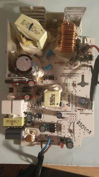
    As in the subject, I have a problem with the Dewalt DCB105 charger. After dismantling and preliminary examination you can see a burnt part of the path that I have repaired. The fuse on the entrance was also blown. mains voltage. After connecting the big buuum and the fuse blown again. I measured the elements and replaced 2 diodes that were damaged and replaced the electrolytes to be sure. In place of the fuse, I connected a 50W 230V bulb. The bulb is on and a faint hum from the transformer is heard.

    If I understood correctly the operation of the bulb instead of the fuse. When the charger was to be operational, the bulb should not light up. As a short circuit, the bulb shines.
  • ADVERTISEMENT
  • #2 16220387
    bearq
    Level 39  
    Yes, a glowing light bulb is a sign of a short circuit. Upload a picture of the charger, start by measuring all the semiconductors, a lot of them are not there. Always start the charger with the bulb in series.
  • ADVERTISEMENT
  • #3 16221927
    adamp9
    Level 16  
    I marked the damaged LEDs, they had a puncture in both directions.
    Dewalt DCB105 Charger Fuse Blowing: Troubleshooting Burnt Circuit Path and Replaced Diodes
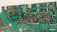
    I selected the damaged and repaired piece of the track.
    Dewalt DCB105 Charger Fuse Blowing: Troubleshooting Burnt Circuit Path and Replaced Diodes
  • #4 16233230
    bearq
    Level 39  
    How do the rest of the transistors in the circuit?
  • #5 16233244
    398216 Usunięty
    Level 43  
    There is an element on the heat sink between the choke on the toroid and the transformer. Check him out.
  • #6 16233821
    adamp9
    Level 16  
    I checked all diodes and transistors except smd. Two rectifier diodes were damaged, I wrote about it in the first post.
    The element between the choke and transformer mounted on the heat sink is a double diode.
  • ADVERTISEMENT
  • #7 16234212
    398216 Usunięty
    Level 43  
    adamp9 wrote:
    I checked all diodes and transistors except smd.

    So the rest of the SMD components ...
  • #8 16234248
    kazikszach
    Level 38  
    I have the same charger in repair.
    Damaged Q2, R20 and smd:
    R16, R17, R18, R19, I can't read their values, maybe you can read them.
    If I have these values, I will try to start it and when it starts, I will suggest something.
    An auxiliary converter is made on the Q2 transistor, these damaged diodes rectify the voltage that supplies it.
  • ADVERTISEMENT
  • #9 16235431
    adamp9
    Level 16  
    R16-393(39k) R17- 101(100r) R18-101(100r) R19-101(100r)
  • #10 16235689
    kazikszach
    Level 38  
    adamp9 wrote:
    R16-393 (39k) R17- 101 (100yr) R18-101 (100yr) R19-101 (100yr)

    Thank you.
    Having these values, I will fight her next week and let me know the effects.
    Just isolate the + bridge and connect it to the mains via a light bulb, so you will be able to tell which inverter is shorting.
  • #11 16236586
    adamp9
    Level 16  
    kazikszach wrote:
    adamp9 wrote:
    R16-393 (39k) R17- 101 (100yr) R18-101 (100yr) R19-101 (100yr)

    Thank you.
    Having these values, I will fight her next week and let me know the effects.
    Just isolate the + bridge and connect it to the mains via a light bulb, so you will be able to tell which inverter is shorting.


    I crossed the plus path behind the bridge and connected the charger through the bulb to the mains. The led on the charger came on and then went out.


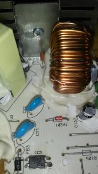
    What is this element marked as TH201. Diode, thermistor?


    Dewalt DCB105 Charger Fuse Blowing: Troubleshooting Burnt Circuit Path and Replaced Diodes
  • #12 16239652
    kazikszach
    Level 38  
    adamp9 wrote:
    I crossed the plus path behind the bridge and connected the charger through the bulb to the mains. The led on the charger came on and then went out.


    What is this element marked as TH201. Diode, thermistor?

    From this it follows that this auxiliary converter is working properly.
    TH201-I haven't figured out what it is.
    After installing the damaged elements and using a light bulb instead of a fuse, the charger tried to move, the light bulb turned on cyclically when the main converter started, and after installing the fuse it worked properly.
    You must have a problem with the main converter.
    As Q2, I used BUT18.
    Thank you for giving the value of the resistors.
  • #14 16411498
    kazikszach
    Level 38  
    Missed when giving values and forgot to write down but it was a few ohms.
  • #15 17045569
    piotrekslup
    Level 11  
    I have a very similar problem only with the DCB107 charger. Two diodes, fuse, resistor r17 and transistor q1 have been damaged. The double diode behind the transformer is good and so are the rest of the semiconductors. What could be the reason?
    The charger is dead after replacing damaged elements. The voltage from the 320V capacitor to Q1 and the transformer and nothing else.
  • #16 17209576
    kazikszach
    Level 38  
    piotrekslup wrote:
    I have a very similar problem only with the DCB107 charger. Two diodes, fuse, resistor r17 and transistor q1 have been damaged. The double diode behind the transformer is good and so are the rest of the semiconductors. What could be the reason?
    The charger is dead after replacing damaged elements. The voltage from the 320V capacitor to Q1 and the transformer and nothing else.

    Today, an identical charger has been repaired, these elements are also damaged, but according to my measurements, the IC1 driver described: 1710-01 is damaged, it has a low resistance on the power supply.
    Where to get such a chip at a reasonable price?
  • #17 17265300
    gruby68
    Level 16  
    I reheat the topic. I need resistor values R39, R40, R41, R31, R32. They evaporated and I have a reading problem. Possibly does anyone have a diagram?
  • #18 17306355
    Omino
    Level 10  
    Described here several times these resistors, repeat:
    R39 104 (100 kΩ),
    R40 121 (120 Ω),
    R41 222 (2K2),
    R31 69c (51.1 kΩ),
    R32 85b (7.5 kΩ)

Topic summary

The discussion revolves around troubleshooting a Dewalt DCB105 charger that experienced a blown fuse and burnt circuit paths. The user initially repaired a damaged circuit path and replaced two diodes, but upon testing with a bulb in place of the fuse, the bulb illuminated, indicating a short circuit. Participants suggested checking all semiconductors, including SMD components, and provided resistor values for further repairs. The user confirmed the operation of an auxiliary converter and identified a potential issue with the main converter. Additional discussions included similar issues with the DCB107 model, highlighting common components that fail, such as diodes, transistors, and resistors. The need for specific resistor values and a damaged IC driver were also mentioned, with requests for circuit diagrams and component sourcing.
Summary generated by the language model.
ADVERTISEMENT