logo elektroda
logo elektroda
X
logo elektroda

KIA Cee'd LED DRL & Position Lamp Failure: Diagnose Burnt Inverter, Voltage Measurement Issues

Kozak_Barabasz 15480 7
ADVERTISEMENT
Treść została przetłumaczona polish » english Zobacz oryginalną wersję tematu
  • #1 16300248
    Kozak_Barabasz
    Level 12  
    Hello,
    I have a problem with one lamp. Well, it does not work at all DRL for daytime driving or position (it is one LED strip that shines strongly in the DRL position and dims as the lights turn on)

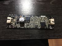
    I glued the lamp out and went to the inverter.
    I measured the voltage at the output and it looks so that without load and applying the same voltage meter to the output of the inverter, it shows less than 6V but it falls off all the time. For a few seconds it goes down to 0V. Of course, when the LEDs are connected, the voltage immediately goes to 0V (even the LEDs will not blink).

    I have a 12V power supply and a good multimeter.
    Can anyone help me, how should I diagnose a faulty item on the following tile? KIA Cee'd LED DRL & Position Lamp Failure: Diagnose Burnt Inverter, Voltage Measurement Issues
  • ADVERTISEMENT
  • #2 16305195
    Kozak_Barabasz
    Level 12  
    No one really help?
  • ADVERTISEMENT
  • #3 16305204
    robokop
    VIP Meritorious for electroda.pl
    At Ceed 2, these lamps were replaced by a guarantee because they just died. A quick autopsy showed that the LEDs themselves were receiving short circuits - working with exceeded current max for maximum brightness.
  • #4 16305778
    Kozak_Barabasz
    Level 12  
    robokop what you say is 100% correct but you have to add one more thing.
    These converters "died" in 2 ways. The first is the one you have given, i.e. a short circuit on the voltage regulator, which led to full electricity for LEDs and simply burned from overheating.
    And the second fault is a short circuit but with the power cut off the output, which saved the LEDs (I checked, my LEDs are good).

    I saw in one workshop their own converter design. It had 3 potentiometers and a coil in the system. I could just look at it quickly. I do not know more.
    The cost of such a system should not exceed PLN 20-30 - just what elements should be there ...
  • #5 16305831
    robokop
    VIP Meritorious for electroda.pl
    Kozak_Barabasz wrote:
    These converters "died" in 2 ways. The first is the one you have given, i.e. a short circuit on the voltage regulator, which led to full electricity for LEDs and simply burned from overheating.
    And the second fault is a short circuit but with the power cut off the output, which saved the LEDs (I checked, my LEDs are good).

    You commit something to a friend. I saw a few damaged lamps, most of it looked like a part of the LEDs did not shine completely, and the rest was flashing - a short in a serially connected branch.
    Kozak_Barabasz wrote:
    I saw in one workshop their own converter design. It had 3 potentiometers and a coil in the system. I could just look at it quickly. I do not know more.
    The cost of such a system should not exceed PLN 20-30 - just what elements should be there ...
    A simple step-down regulator, which is full on the Allegro - you only need to know the branch voltage and the required current.
  • ADVERTISEMENT
  • #6 16308326
    Kozak_Barabasz
    Level 12  
    If I did not fuck anything, the diagram should be good.
    As I wrote earlier, 2 wires come out of the inverter.
    LEDs are 15 and are divided into 2 sections. The first has 8, the second is 7.
    At the beginning of the bar there are 2 resistors with the value of 25ohm
    I learned that the output voltage should be 9-9.5V.
    I do not have, and even if I had a working lamp, I would not want to break it down to test the efficient converter.


    I have experimentally connected a small 12V battery to these LEDs. The consumption was 4.5A, which is over 50W. Of course, I gave it for 2-3 seconds. They shone very brightly and quickly became warm - obvious.
    So the current and voltage regulator is a known duty.
  • ADVERTISEMENT
  • #7 16330035
    Kozak_Barabasz
    Level 12  
    Okay, I was able to buy a compact lamp from a well-known portal for the buck.
    The converter was, for good, whole. It has other elements but it should not affect the final values.

    At "idling", i.e. without load, the final output voltage is practically coincident with the input voltage. This is both after + 12V for green or red power cord (DRL and position).
    This probably means that there is no voltage regulator there, only the current regulator will be used.

    Now measurements (my multimeter is not accurate when measuring current):
    - green power supply (DRL), output voltage 6.58V, current 0.92A
    - red supply (position), output voltage 2.755V, current 0.06A

    Does anyone design such tiles with 2/3 potentiometers?

    PS: The graph above is out of date with an output voltage of 9.5V, which was estimated
  • #8 16330616
    grala1
    VAG group specialist
    If you have less than 1A then you can think about connecting two sets of AVT1553 - one for DRL and the other for a stop.

Topic summary

The discussion revolves around a malfunctioning LED DRL and position lamp in a KIA Cee'd, where the user reports voltage issues from the inverter. The voltage drops below 6V and falls to 0V when the LEDs are connected, indicating potential inverter failure. Responses suggest that similar issues have been observed in other Cee'd models, often due to short circuits in the LEDs or the inverter. Users recommend diagnosing the inverter and considering alternative designs for voltage regulation. Measurements indicate that the output voltage is significantly lower than expected, and suggestions include using a step-down regulator or a custom converter design with potentiometers to manage voltage and current effectively.
Summary generated by the language model.
ADVERTISEMENT