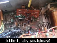
bulasty82 wrote: power terminals burned complementary pair and R-538 emitter resistor I replaced the terminals and the emitter resistor measured 100 ohms the same between transistors on emitters 200 ohms value, the 1.25A fuse blown when the power was turned on
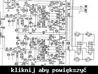
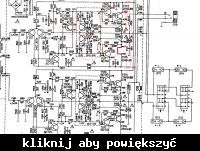
The final stage is made of T510 transistors from T514 and T512 from T516, so you should carefully check all of them. The more so as the collector short-circuit with the T516 emitter caused its complete bypassing and overloaded most of the elements.
From a physical point of view, it is unlikely that the resistance 0.22-0.33 overloaded, suddenly overheated would have a value of 100 (most often the wire resistor burns out - opening). Rather, you should look for an erroneous measurement with a meter on the wrong measuring range or a used power battery.
It is most sensible to run this amplifier without the T514 and T516 transistors, using 32? -600? as the headphone load. For small controls the amplifier should work properly without the slightest audible distortions.
For larger signals at the input, the distortions resulting from clipping the tops of the sinusoid should be clearly audible. By reducing the input signal, the amplifier should continue to operate stably without distortion. Nothing should be overheated.
Then you can insert terminal transistors and emitter-equivalent resistors of 47? -51? / 5-20W. In this configuration, we have them securely protected and, as before, we can safely check the correct operation of the amplifier with low input control with the output being loaded with headphones. The amplifier should work properly as before, the emitter-equivalent resistors should not heat up, the unbalance DC voltage at the amplifier output should be small, several dozen mV. And the quiescent current, obviously measured using the technical method, should not be greater than the nominal one.
After successful results of such tests, it is possible to install target emitter resistors, start the amplifier, checking the quiescent current and unbalance voltage, check the operation of the amplifier on a load of 8? -16?, not necessarily a wire resistor on the loudspeaker.
After all these tests, you can start setting the target quiescent current of the amplifier in accordance with the accepted rules of procedure.
bulasty82 wrote: I will give the factory 4700 microF capacitor for this I will connect two 3300 microF capacitors in series and I will have a 2x8000 microF / 40 V capacitor
Capacitors connected in series have a smaller capacity and a higher operating voltage, with parallel connection the capacity increases while maintaining the rated operating voltage.
In my opinion, it makes no sense to use much too large capacities for this amplifier, it can only cause excessive load on the transformer, especially when forcing the amplifier and the initial connection of the amplifier to the mains.

 Added after 11 [minutes]:
 The damage seems to have been caused by a slightly different short circuit between the base and the collector. In general, when this type of damage occurs, it is worth replacing all the transistors in the final stage, the more so because their price is negligibly small compared to the replacement of the current transistors several times.
Then there is the question of setting the quiescent current and checking the imbalance voltage.
Does your colleague know how to do it?


