Hey,
In a word, I wanted to say, I go to the first class of electronic technical school and for a short time I learn to program the famous Arduino. I am still a beginner, so please take this into account when analyzing my idea and possible answer, so that I can understand what and how
I am a fanatic of the stage, all kinds of audio equipment and lighting. A few days ago I set myself a goal to make a moving head - so that I could practice the basics of electronics in practice, but also to improve my assessment of digital circuits and eie measurements at school.
If you are not in the subject what the moving head is, then I am hurrying with the explanation that it is a reflector, whose "base" is rotating and the 2 arms that hold it allow you to move up and down. All together allows the light pole to move in almost all directions. In television programs such as "Jaka tym melodia" or in cabarets, you can often find them placed on the floor in the background, or at concerts as light poles moving.
Will be controlled from a physical driver, which will also be made by me and will also be made on the basis of arduino (radio control will be up to about 1 kilometer).
The mere movement of the "head" is not a problem for me, just the transfer of data. The biggest problem for me so far is to design a simple system, up to 90 watt RGB LED, which will change the voltage value depending on the level of PWM signal filling.
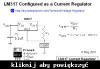
On the internet, I can not find anything that helps me find it. I found only something like this:

I wonder if something like this will work. From my (beginner) point of view there is nothing to do, because the PWM signal is nothing but a change in the presence of voltage or its absence, i.e. the diode would simply flash quickly. The more that I do not know how the transistor itself would behave considering its propagation time. From the first lessons of arduino, I learned that by controlling a single diode, a capacitor must be connected, which will be the voltage "averaged"
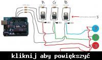
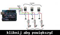
I see the scheme of this, so that three signals come out of arduino, which separately control each color of the RGB diode (3 * 30W), then go to the gates of the transistors, which control the voltage on the emitter.
The auction number on the Allegro with the diode I plan to use (I can not add a link): 6679861262
I know that these are very basic questions, but:
1. At what value given on the gate the transistor will fully control the given voltage.
2. Where it is best to insert a fuse / and other safety devices.
I am asking for help and the best explanation for that. I know that these are the basics, but at school it is really hard to understand something exclusively from theory.
In a word, I wanted to say, I go to the first class of electronic technical school and for a short time I learn to program the famous Arduino. I am still a beginner, so please take this into account when analyzing my idea and possible answer, so that I can understand what and how
I am a fanatic of the stage, all kinds of audio equipment and lighting. A few days ago I set myself a goal to make a moving head - so that I could practice the basics of electronics in practice, but also to improve my assessment of digital circuits and eie measurements at school.
If you are not in the subject what the moving head is, then I am hurrying with the explanation that it is a reflector, whose "base" is rotating and the 2 arms that hold it allow you to move up and down. All together allows the light pole to move in almost all directions. In television programs such as "Jaka tym melodia" or in cabarets, you can often find them placed on the floor in the background, or at concerts as light poles moving.
Will be controlled from a physical driver, which will also be made by me and will also be made on the basis of arduino (radio control will be up to about 1 kilometer).
The mere movement of the "head" is not a problem for me, just the transfer of data. The biggest problem for me so far is to design a simple system, up to 90 watt RGB LED, which will change the voltage value depending on the level of PWM signal filling.
On the internet, I can not find anything that helps me find it. I found only something like this:

I wonder if something like this will work. From my (beginner) point of view there is nothing to do, because the PWM signal is nothing but a change in the presence of voltage or its absence, i.e. the diode would simply flash quickly. The more that I do not know how the transistor itself would behave considering its propagation time. From the first lessons of arduino, I learned that by controlling a single diode, a capacitor must be connected, which will be the voltage "averaged"
I see the scheme of this, so that three signals come out of arduino, which separately control each color of the RGB diode (3 * 30W), then go to the gates of the transistors, which control the voltage on the emitter.
The auction number on the Allegro with the diode I plan to use (I can not add a link): 6679861262
I know that these are very basic questions, but:
1. At what value given on the gate the transistor will fully control the given voltage.
2. Where it is best to insert a fuse / and other safety devices.
I am asking for help and the best explanation for that. I know that these are the basics, but at school it is really hard to understand something exclusively from theory.


