logo elektroda
logo elektroda
X
logo elektroda

Flashing Aliexpress LN882H based KA061B3-istb Bulbs: Switching I2C BP5758 to PWM Control

apsis 480 18
ADVERTISEMENT
  • Helpful post
    #1 21466362
    apsis
    Level 6  
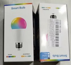
    I have bought some Aliexpress bulbs KA061B3-istb based on LN882H.
    Here is link:
    https://www.aliexpress.com/item/1005007195901....order_list.order_list_main.52.6cd81802ivIuiG
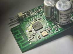
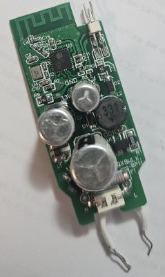
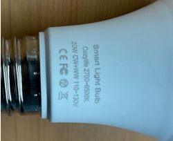
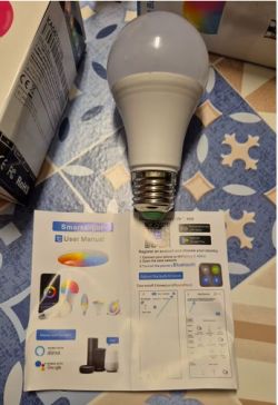
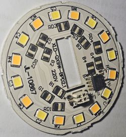
    Here are pictures
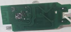
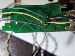
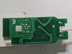
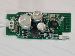
    Printed circuit board with green laminate and conductive traces.
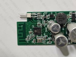
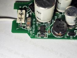
    Close-up of a circuit board with various electronic components, such as capacitors, a chip, and conductive traces.
    Close-up of a circuit board with various components, including capacitors and a chip.
    Smart light bulb with visible technical markings on the socket.
    A smart LED bulb is on a table next to a user manual.
    Smart Bulb packaging with colorful graphics.
    Advertisement for a smart LED bulb with voice control and mobile app functionality.
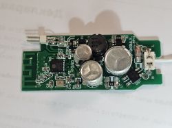
    LED circuit board :

    After many re-solders /unstable 3.3V supply I believe/ I managed to flash them with this tool: https://www.elektroda.com/rtvforum/topic4045532.html
    I did some dumps following this guide, but they were partial and could not successfully flash: https://www.elektroda.com/rtvforum/topic4028087.html

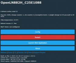
    Now I am here:
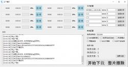
    Software interface in Chinese for device memory configuration.
    User interface with device information for OpenLN882H, configuration, restart, and web application launch options.

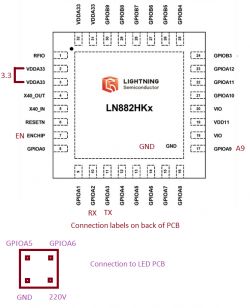
    Here ARE connections:
    Connection schematic of the LN882HKx integrated circuit with pin labels.

    If you need any dumps or tests - I now have stable 3.3V supply and 4 more bulbs.

    My intention for these ones is to use them with another driver not the original I2C BP5758, instead I want both PINS used for I2C to do PWM for Cold and warm white.
    Keeping that in mind if I can keep few lamps as-is with BP5758 - that be great.
    I have never used anything other than stock apps, however I hate having more and more APPS, so any advice on how to proceed from here is welcomed /I have no idea/.

    I have Libvirt based KVM and Raspberry at home - so Please, let me know what to install and how to configure
    Please note I am good with Analog Electronics and Linux/Windows, however my programming skills are NONE.

    AI: Could you provide more details about the current firmware or tool you used for flashing the bulbs? This will help in understanding compatibility issues.
    GUI flash tool for LN882H version 3.0.1 /https://www.elektroda.com/rtvforum/download.php?id=1205991/
    AI: Can you describe your current setup or configuration of the bulbs and any specific errors you encountered during the process?
    I only had issues with stable 3.3V supply
    Do you have a problem with Raspberry? Ask question. Visit our forum Raspberry.
  • ADVERTISEMENT
  • #2 21466419
    insmod
    Level 22  
    >>21466362 While any pin on LN can be configured as PWM, i don't exactly know what you are trying to accomplish here.
    Do you want to remove BP5758 from led board, or swap board altogether?
    If you want to remove BP5758 and use PWM for driving leds, that's a bad idea.
  • ADVERTISEMENT
  • #3 21466450
    apsis
    Level 6  
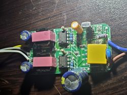
    >>21466419 I have another driver(s) from IR remote lamps using two separate Bright power PWM based drivers (dual BP2958 ) - one for CW and one for WW.
    Example:
    View of a circuit board with electronic components like capacitors and BP2958 drivers on a wooden background.

    I would like to use this board, as it has integrated AC to 3.3v supply , connect common ground, remove the chip from the original board and supply PWM from this one.

    This way i can get rid of the horrible function to change color and brightness on fast switch on/off

    Basically i do not want to use the LED board at all but control another driver designed for PWM
    Making non-smart 50+USD fixture in to a smart one - as i have 2 /got smart replacements already/ but i know people with such /allot/ and i will have 2 fixtures and 5 boards from these smart bulbs to play with.
  • ADVERTISEMENT
  • Helpful post
    #4 21466517
    insmod
    Level 22  
    >>21466450 Well, you can try it. I did say that pwm is available on all pins.
    You would probably have to add some level shifter, since i doubt that those leds use 3.3v. And something to control how much power those leds receive, because i know bp5758 also controls that.
  • Helpful post
    #5 21466579
    p.kaczmarek2
    Moderator Smart Home
    So you're basically trying to ... use LN882H as Arduino replacement? Well, you can certainly do that, we have both PWM pins with predefined LED driver, and PWM_ScriptOnly role if you don't want to get auto LED controls as well.
    The remaining connection is not really related to OpenLN882H/OpenBeken itself, it's rather a generic question how would you drive your LED with PWMs?

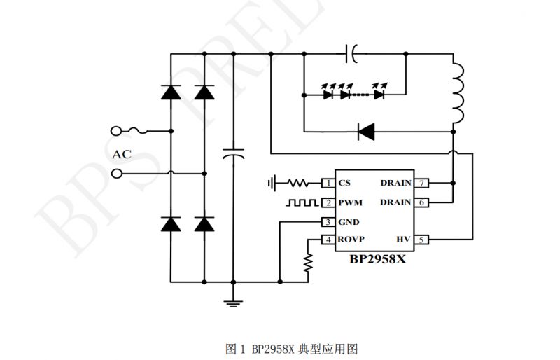
    But to answer your question more directly... I can see that your target board is using BP2958 drivers, right? There is some information on them in the web:
    Block diagram with BP2958X circuit for power and energy conversion.
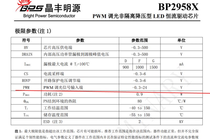
    But will it work with 3.3V PWM?
    Technical parameter table for the BP2958X chip with Chinese descriptions.
    Table fragment with PWM data, including voltage values in rows.
    Well, according to the datasheet, the high state on PWM pin is considered when the voltage is above 2V (typical), so I would say, yes, you can control it directly from LN882H.

    Of course, exercise extreme caution when connecting LN882H to your board, do not touch it unless it's disconnected from mains, remember that capacitors can still hold charge even after you disconnect it, and make sure to have common ground when connecting the WiFi module.

    Futhermore, what kind of 3.3V power supply is on your target board? Is it really 3.3V? Too high voltage can easily damage WiFi modules.
    Helpful post? Buy me a coffee.
  • #6 21466680
    apsis
    Level 6  
    Hello,

    The Aliexpress lamp board itself has proper pulse mode power supply for the chip - I will be using that instead of the shitty one on the BP2958 - which is based on zener diode and resistors.
    I have no doubts I can connect the two boards - I can deal with it and have gone through the datasheets.
    Yes I will use LN882H board as ESP replacement since it does have WiFi and included PSU circuit.

    The question is - how to work with OpenLN882H/OpenBeken.

    As far as I see I need VM or Raspberry with Home Assistant OS - https://www.home-assistant.io/installation/raspberrypi/
    What else do I need? seems I have to write some json for config, however as I have never tried Home Assistant I have no clue how to add the lamp, so I need help there.

    Also if I want to use it as is with the BP5758 /I do have couple lights/ how do I configure the I2C communication.
  • #7 21466694
    insmod
    Level 22  
    >>21466680
    You can use anything with mqtt (and writing configs for that), Home Assistant (there is a discovery thingy in OpenBeken, so one click and device shows in HA), or just connecting to device directly and controlling it via http main page.
    Since you have already traced pins, set them up in config, one as BP5758D_CLK, other as BP5758D_DAT.
    Then experimentally adjust color map in console via BP5758D_Map (usually it is BP5758D_Map 2 1 0 3 4), you can also adjust current via BP5758D_Current (first arg is for RGB, second is for CW, default is 13mA).
  • #8 21466704
    p.kaczmarek2
    Moderator Smart Home
    apsis wrote:

    The Aliexpress lamp board itself has proper pulse mode power supply for the chip - I will be using that instead of the shitty one on the BP2958 - which is based on zener diode and resistors.

    Both lamps have non-isolated power supplies, right? So if you connect their to mains randomly, you have 50% chance of blowing them up. You need to know which wire is live and which is neutral. And remember about common ground...
    Helpful post? Buy me a coffee.
  • #9 21466708
    divadiow
    Level 34  
    also, please try LN882H firmware backup again on another bulb :)
  • #10 21466776
    apsis
    Level 6  
    >>21466704 No issues with that.
    It's easy to measure or check full bridge rectifier pins to identify ground on both.
    Positive will always be relative to it.
    Can use small low wattage resistors to play it safe
  • Helpful post
    #11 21466780
    p.kaczmarek2
    Moderator Smart Home
    Do you actually even need Home Assistant? With OpenBeken you can have all controls in the OBK page, you can also enable SSDP driver to get your device visible in the "My Network" view in Windows...
    Helpful post? Buy me a coffee.
  • #12 21466783
    apsis
    Level 6  
    >>21466708 Will do
    Here is the best I have so far, not sure it is complete, but the best I managed out of 10's of attempts:
    https://nas.mode-x.org/s/oJ6TDpRANiznFix

    Added after 2 [minutes]:

    >>21466780 Thank you - this is one way I can do it.
    Can you share link to some guide or quick explanation as I do not know where to start.
    Just in case I spun UP Home assistant VM just now.
  • #15 21467383
    apsis
    Level 6  
    >>21466793 I tried dumping brand new board with this command: python LN882H_Flash_Dumper.py COMx flashdump
    following this guide: https://www.elektroda.com/rtvforum/topic4028087.html

    However it always stops at random point.
    Is there another way ?

    ps.: your Linux dump script requires some very hard to get working ymodem thing:
    root@raspberrypi:~# pipx install YModem
    'ymodem' already seems to be installed. Not modifying existing installation in '/root/.local/pipx/venvs/ymodem'. Pass '--force' to force installation.
    root@raspberrypi:~# python dumper.py ttyUSB0
    Traceback (most recent call last):
    File "/root/dumper.py", line 34, in <module>
    from YModem import YModem
    ModuleNotFoundError: No module named 'YModem'


    Here are more board pics:
    Circuit board with various electronic components, including capacitors and a coil.
    Close-up of a green PCB with soldered wires in various colors.
    Close-up of a circuit board with markings such as TX, RX, EN, and GND.
    Close-up of a green printed circuit board with electronic components.
    Close-up of a circuit board with visible capacitors and other electronic components.
    Printed circuit board with various electronic components.

    Added after 17 [minutes]:

    >>21466799 Any guide on how to configure for PWM on pins GPIO5 and GPIO6 or I2C communications on same pins ?
    I mean how to configure the chip itself to know and if possible report what it is - this is what I need.

    - I got it!
  • ADVERTISEMENT
  • #16 21467756
    divadiow
    Level 34  
    apsis wrote:
    However it always stops at random point.
    Is there another way ?


    I'm wondering if maybe your wires are too long. Where possible mine are usually 10-15cm max and are the thin hobbyist breadboard type gauge.
  • #17 21468812
    apsis
    Level 6  
    >>21467756 It's not the wires for sure, even tested wires less than 2cm.
    Could still be a power thing, but I doubt that as programming with this https://www.elektroda.com/rtvforum/topic4028087.html never worked.
    Only this tool did the job : https://www.elektroda.com/rtvforum/topic4045532.html
    Thinking of another ways however if a better dump tool is available, one that can tolerate some errors - let me know
  • #18 21471519
    divadiow
    Level 34  
    apsis wrote:
    ps.: your Linux dump script requires some very hard to get working ymodem thing:
    root@raspberrypi:~# pipx install YModem
    'ymodem' already seems to be installed. Not modifying existing installation in '/root/.local/pipx/venvs/ymodem'. Pass '--force' to force installation.
    root@raspberrypi:~# python dumper.py ttyUSB0
    Traceback (most recent call last):
    File "/root/dumper.py", line 34, in <module>
    from YModem import YModem
    ModuleNotFoundError: No module named 'YModem'


    oops. yes, sorry, that dumper should be sat in amongst all the other files from https://github.com/mandl/LN882Loader
  • #19 21477046
    apsis
    Level 6  
    >>21466793 I bought fairly expensive USB to UART based on CH330N Opto isolated with ADUM1201 and even power isolated.

    Thanks to this I got what I believe is a proper dump: https://nas.mode-x.org/s/oJ6TDpRANiznFix
    Hope this will do.

    Interesting part is I had no issues flashing with the old USB to UART I had laying around.

Topic summary

The discussion revolves around flashing Aliexpress KA061B3-istb bulbs based on the LN882H chip, specifically focusing on switching from I2C control via BP5758 to PWM control. The original poster successfully flashed the bulbs after overcoming issues with unstable power supply and partial dumps. Participants discuss the feasibility of using the LN882H as a PWM controller, the need for level shifting due to voltage differences, and the integration of the LN882H with other PWM drivers like BP2958. There are also inquiries about using Home Assistant for configuration and control, with suggestions for setting up I2C communication and adjusting parameters for LED control. The conversation highlights challenges in dumping firmware and the importance of proper wiring to avoid damage.
Summary generated by the language model.
ADVERTISEMENT