In the article we will describe the methods of testing ASK / FSK signals used in keyless systems in modern cars.
Rigol Technologies expanded the Radio Frequency (RF) range test system of the DSA800 Spectral Analyzer from the additional test features of passive proximity (keyless) lock systems. The Rigola solution is very convenient to use and much cheaper than other test systems on the market.
Passive Keyless Entry (PKE) systems are electronic systems primarily used to open cars or buildings without mechanical keys. Such locking systems work with a passive element (key) that is activated by a device (e.g. a car) sending a periodic signal to the environment. One of the most widespread examples of such a system is the proximity car opening system. The vehicle always sends a constant low frequency (LF) signal around 130 kHz to the surrounding environment. If the correct key is near the vehicle (about 1-1.5 m), it recognizes the LF signal and sends back the correct ID (ID) in the form of an RF signal (in the UHF band) with ASK or FSK modulation. When the car door is opened manually, the system is unlocked. In some solutions it is also possible to start the car engine with the button when the key is in the vehicle cabin, or to open the trunk. The frequency of the UHF signal used in PKE systems depends on the location. In Europe, the 433 MHz carrier frequency of the ISM2 band is mainly used. Such applications also use the 868 MHz carrier frequency in Europe, which is not a frequency in the ISM band. In the USA and Japan, the frequency of 315 MHz is mainly used.
Two types of proximity lock operation procedures are possible:
1) The vehicle sends the LF signal with a short wake up signal
[letter: 128f17176f]
[*: 128f17176f] During the defined period, the vehicle sends the LF signal to the environment with short information (excitation signal).
[*: 128f17176f] If the proximity key is close to the car, it sends back a confirmation signal (UHF).
[*: 128f17176f] The key and the car start data transmission with the identification data (ID) check.
vCar sends the ID to the key. If the identification data is correct, the key sends its code. If the code is correct, the vehicle unlocks the door, allowing it to be opened.
[/ letter: u: 128f17176f]
2) The vehicle sends the LF signal with its ID
[letter: 128f17176f]
[*: 128f17176f] During the defined period, the vehicle sends the LF signal with its identification data to the environment.
[*: 128f17176f] If the proximity key is close to the car and the received ID is correct, the key sends its identification code back. If this code is correct, the car can be opened. [/ List: u: 128f17176f]
Spoiler:
1 UHF (Ultra High Frequency) = band of decimeter electromagnetic waves in the range 300 MHz to 1000 MHz.
2 ISM (Eng. Industrial, Scientific and Medical) = radio wave band intended initially for industrial, scientific and medical use, and now also private. The ISM defined two types of band: type A and type B. B band type can be used without a license. The most common ISM frequency range is the 2.4 GHz to 2.5 GHz band, which is used by wireless data transmission systems in computer networks.
3 Source: Relay Attacks on Passive Keyless Entry and Start Systems in Modern Cars, Aur'elien Francillon, Boris Danev, Srdjan Capkun Department of Computer Science ETH Zurich 8092 Zurich, Switzerland, §2.2
FSK modulation - modulation with frequency keying
FSK (Frequency Shift Keying) modulation is a type of digital modulation. This modulation modulates the carrier wave with a digital signal, and changes in the frequency of the carrier wave are discrete. The basic form of this modulation is 2FSK modulation. 2FSK modulation is used e.g. in proximity systems such as car opening systems or tire pressure monitoring systems. In the simplest form of 2FSK modulation the two digital states "0" and "1" (2FSK with 1 bit / symbol) are transmitted at two different frequencies.
These two frequencies modulate the carrier wave and both have the same spacing from the carrier frequency. The difference between FSK modulation and analog FM modulation is that in FSK modulation the two transmitted frequencies change in tact with binary data, and in FM modulation the carrier frequency changes according to the analog modulation signal.
The separation of the two key frequencies from the carrier frequency is called the FSK deviation:
* FSK deviation = ?f
* fcarrier (carrier frequency) +- ?f
Example:
Figure 1 shows a 2FSK modulation signal with ?f = 40 kHz and fcarrier = 866 MHz
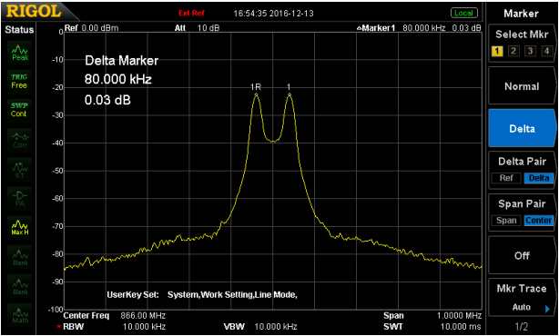
Fig. 1 2FSK signal with 40 kHz deviation and 866 MHz carrier frequency measured with DSA832E instrument
The distance between the two characteristic frequencies is 80 kHz:
fmax = fcarrier + ?f = 866 MHz + 40 kHz
fmin = fcarrier - ?f = 866 MHz - 40 kHz
fmax - fmin = 80 kHz
The characteristic frequency interval is 2 x FSK deviation:
? (f2 - f1) = 2 x ?f
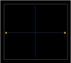
Fig. 2 2FSK modulation constellation diagram, carrier frequency is in the center of the screen.
The test results illustrated in Figures 3 and 4 show different types of relevant measurements:
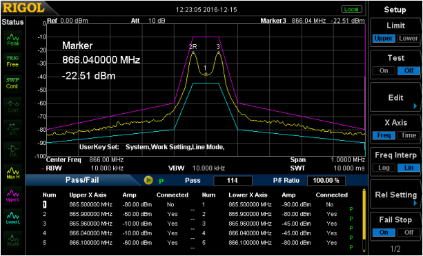
Fig. 3 Good / Bad mask for curve analysis
The signal should not exceed the user-defined lines of the Good / Bad mask (Fig. 3). The test can be performed with DSA832, DSA832E or DSA8754.
The absolute values of both frequencies can be measured (Fig. 4, 2R and 3D markers).
The carrier frequency interval can be checked with the marker function (fig. 4, marker 1D).
It is also possible to measure the value of the power difference of both frequencies (Fig. 4, 2R and 2D markers).
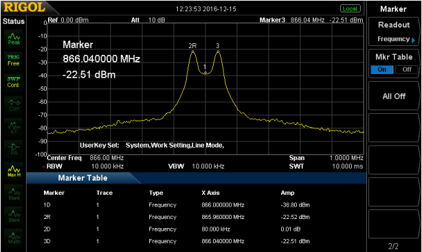
Fig. 4 Measured characteristic parameters of the 2FSK signal (see Marker Table)
Another available measurement is bandwidth occupancy analysis (OCP). The OCP function measures the frequency range within which 99% of the spectral power of the signal is contained. The signal carrier frequency is in the middle of this range (see Figure 5). OCP can be measured with the DSA800 with the option DSA800-AMK (5).
The OCP value for the 2FSK signal is calculated from the relationship:
OCPBW = baud rate + 2 x ?f (6)
For example: baud rate 10k symbols / s and frequency deviation 40 kHz
OCPBW = 10k symbols / s + 2 x 40kHz = 90kHz
Spoiler:
4 Measurement speed of DSA832, DSA832E and DSA875 (10ms sweep time: processing time 30-40ms): ~ 50ms measurement speed is available in normal operation.
5 The following measurements are available with the DSA800-AMK option: Time Power (measurement of power as a function of a given carrier frequency), Adjacent Channel Power (measurement of power in adjacent channels), Channel Power (measurement of power and power density in a channel), Occupied Bandwidth ( Occupancy Measurement), Emission Bandwidth, S / N (Signal / Noise Ratio measurement), Harmonic Distortion, TOI (3rd order intermodulation distortion measurement).
6 Due to the influence of the Roll Off Factor no. 0.35, OCP will be less than calculated.
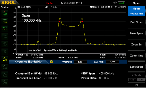
Fig. 5 Measurement of the bandwidth occupation (OCP) of the 2FSK signal
Filtering
The purpose of filtering is to give digital pulses a smooth rounded shape for better spectral measurement results and bandwidth reduction. Different types of filters can be selected in ULTRA IQ STATION Rigola software. For FSK modulation, a special Gaussian filter is available to limit the bandwidth before transmission. Filtering the FSK signal with this type of filter results in a signal conversion to GFSK modulation. In this software it is possible to set the bandwidth extension factor (? = B * T), the pulse length (number of samples per pulse during one bit) and oversampling (increase the sampling rate for better compliance with the sampling theorem, so that a simpler filter can be used. reconstruction). The Gaussian characteristic is shown in Figure 6. The filter length is the product of the pulse length and the ovwersampling value.
The band extension factor ? is calculated from the values:
[letter: 128f17176f]
[*: 128f17176f] Gaussian characteristic band (@ -3dB):
[*: 128f17176f] duration of one bit: TBit [/ list: u: 128f17176f]
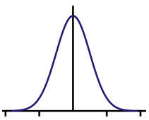
Fig. 6 Gaussian characteristic
The 2FSK signal can be generated in the ULTRA IQ STATION software and loaded into the RF signal generator with the IQ option (DSG3030-IQ or DSG3060-IQ (8).
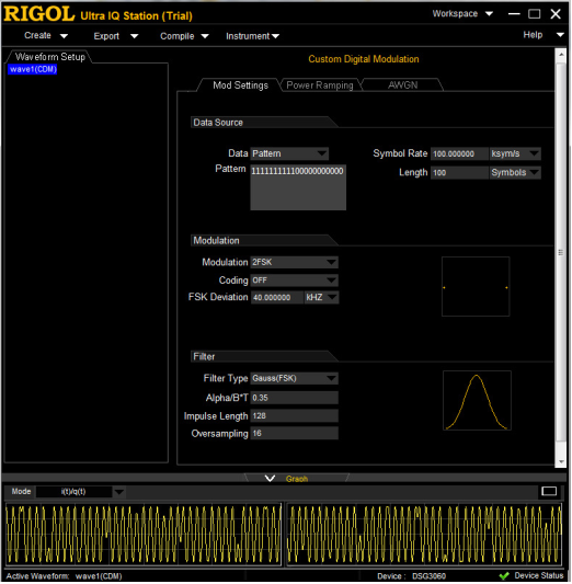
Fig. 7 Generation of 2FSK signal in ULTRA IQ STATION software
Spoiler:
7 Drawing source: Wikipedia.org
8 DSG3030-IQ: 9kHz to 3GHZ; DSG3060-IQ: 9 kHz to 6 GHz; The IQ modulator is an option and also includes external I and Q analog inputs and outputs.
7 Drawing source: Wikipedia.org
8 DSG3030-IQ: 9kHz to 3GHZ; DSG3060-IQ: 9 kHz to 6 GHz; The IQ modulator is an option and also includes external I and Q analog inputs and outputs.
The clock frequency in the generator sets the output frequency of the array synthesis clock. The clock frequency is calculated from the oversampling value and the bit rate (in our example of 2FSK modulation, one transmitted symbol contains one bit).
Clock frequency = oversampling value * bit rate
S1220 software for 2FSK demodulation
Rigol provides (as an option) an ASK / FSK software demodulation solution in the form of the S1220 software package. This software works with the DSA832, DSA832E and DSA8759 analyzers. ASK demodulation is described at the end of this article.
[letter: 128f17176f]
[*: 128f17176f] The software displays the waveforms of the symbols of the modulated signal.
[*: 128f17176f] You can analyze eye diagrams, which is especially important when analyzing the jitter of the tested signal.
[*: 128f17176f] It is possible to set the signal pattern as a reference waveform. Each time a pattern is transmitted, it is marked in yellow.
[*: 128f17176f] Carrier power, frequency deviation and carrier frequency offset can be measured.
[*: 128f17176f] Manchester encoding is supported.
[*: 128f17176f] You can save and load configuration data.
[/ letter: u: 128f17176f]
2FSK signal settings are shown in Figure 8.
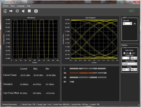
Fig. 8 S1220 software for ASK / FSK demodulation
Spoiler:
9 The analyzer must be in the DMA (FFT) mode. The analyzer control via the S1220 software is only possible in the DMA mode.
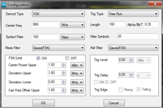
Fig. 9 Configuration for FSK modulation in the S1220 package
Measure FSK signals with DSA815, DSA705 and DSA710 instruments
The S1220 software is intended only for the DSA832 (E) / DSA875 analyzers. The measurement speed of the DSA815, DSA705 and DSA710 is slower than that of the DSA832 (E) / DSA875 and too slow for 2FSK signals. Rigol solved this problem by introducing a new option for continuous signal recording (SSC-DSA) 10. With the SSC-DSA option, it is also possible to analyze 2FSK signals measured with DSA815, DSA705 and DSA710 instruments. With this option, the analyzer is switched to the FFT mode with a faster signal registration rate. This option enables parallel measurements of FSK signals (up to three 2FSK signals) up to 1.5 MHz (see fig. 10) directly via the instrument without any additional software.
The option has three main characteristics:
[letter: 128f17176f]
[*: 128f17176f] Real-time spectrum display (RT Trace).
[*: 128f17176f] Maximum Hold function.
[*: 128f17176f] Analysis of the recorded 2FSK signal, which includes:
- also the maximum value memory function in parallel with the continuous measurement,
- Pass / Fail test against user-set boundary lines,
- activation of two marker lines,
- measurement of the two frequencies of the 2FSK signal, the amplitude of both, the frequency deviation and the carrier frequency offset.
[/ letter: u: 128f17176f]
Spoiler:
10 This option is only available for the DSA705, DSA710 and DSA815 instruments.
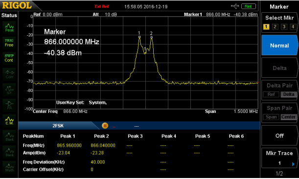
Fig. 10 Measurement of the 2FSK signal with the DSA815 instrument with the SSC option
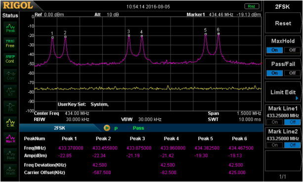
Fig. 11 Measuring three 2FSK signals simultaneously with max hold function
ASK modulation - modulation with amplitude keying
ASK modulation (Amplitude Shift Keying) is also a type of digital modulation used in eg keyless locking systems or beacons. In the simplest form, the two digital signal states "0" and "1" are multiplied with the carrier frequency (see figures 12 to 14 ). c (2FSK with 1 bit / symbol) are transmitted at two different frequencies. On / Off Keying (OOK) is used in keyless systems using ASK modulation.
Two-state keying (OOK):
[letter]
[*] In state "1" the carrier wave is transmitted; at state "0" the carrier is turned off.
[*] ASK modulation is 100% (see fig. 14).
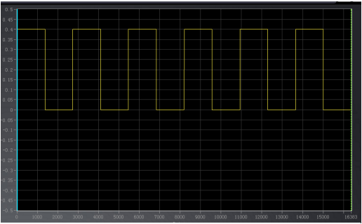
Fig. 12 Pulse sequence "1" and "0" (digital signal)
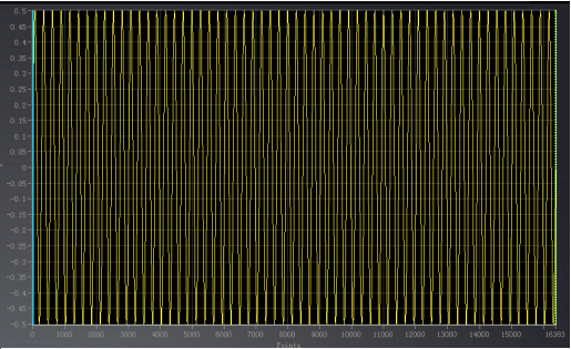
Fig. 13 ASK carrier modulus (sine wave)
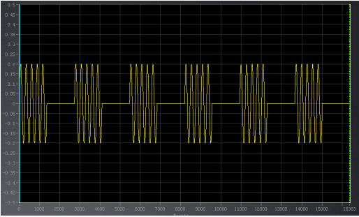
Fig. 14 ASK modulation (digital signal * carrier)
The ASK signal may also be transmitted with a constant carrier wave. In this case, state "0" is transmitted with a lower amplitude than state "1". ASK modulation can be e.g. 10% (e.g. in so-called near field communication [NFC] systems with a code rate of 424 kbps).
The ASK modulation index is calculated from the following formula:
[letter]
[*] m = (AB) / (A + B) * 100
[*] If m = 8 ~ 14% then ASK modulation is ~ 10%.
[*] The modulation depth is B / A

Fig. 15 10% mod ulacja ASK
ASK modulation band is defined by the relationship:
B = 2 x baud rate
ASK signals can also be generated by a DSG3000-IQ series RF signal generator (eg DSG3060) with ULTRA IQ STATION software (see figure 16).
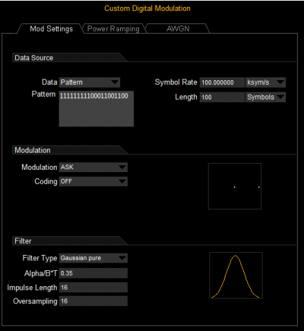
Fig. 16 ULTRA IQ STATION settings for ASK signal generation
The frequency range is shown in Figure 17. The ASK spectrum is equal to 2 x the transmission rate. Such a spectrum is visible with different signal lines. It makes sense because the expected spectrum in this form of transmission is not only an OOK signal.
[letter: 128f17176f]
[*: 128f17176f] Time domain burst is represented by the SI function (sinx / x) in frequency variation.
[*: 128f17176f] Pulse train (constant sequence 0101 ...
[*: 128f17176f] The multiplication with the carrier frequency results in a shift of this function to the carrier frequency.
[/ letter: u: 128f17176f]
The digital signal is visible in the zero span mode of the analyzer (see Figure 18). In this mode, you can analyze the impulse train in the time domain.
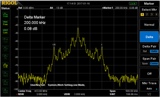
Fig. 17 Spectrum of the ASK signal
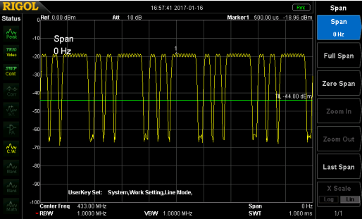
Fig. 18 View of the ASK signal in the zero span mode
The ASK signal can also be analyzed with the S1220 Rigola ASK-FSK demodulation software. The settings and images for analysis are the same as for the analysis of 2FSK signals.
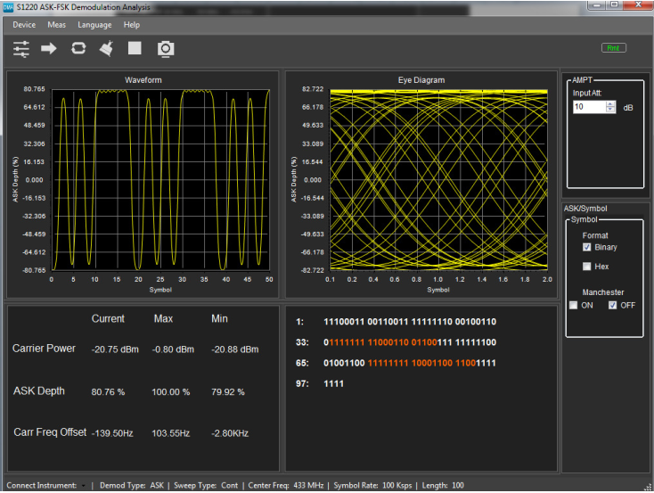
S1220 Rigol Software

https://www.ndn.com.pl/
*Sponsored article


