Hello
I have a few questions about electrical installation in a single-family house. I would like to estimate the costs that await me and supplement my knowledge on the implementation of such an installation.
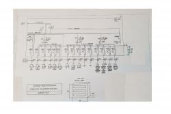
Installed power for the whole building Pi = 18.0 kW, Po = 16.1 kW, Io 24.0 A. The YKYżo 5x10 cable was selected from the cable joint to T1, whose Idd = 62 A and secured in the joint; pre-meter 3 x Bm Wtz 40 A and pre-meter R303 B - 25 A.
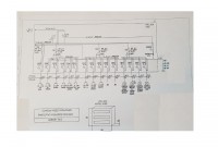
In the diagram behind the FR, the wires go to the RCD of individual "sections", then to individual circuits. In addition, the diagram shows the 4xdehnguard t275 surge arrester. S303B40A is visible between the FR and the limiter, why this overcurrent switch? Or am I reading this diagram wrong? Moreover, the draft describes the R303 B - 25 A post-test protection. How does this compare to the RCD of a 3-phase socket in the garage (40A) and the previously mentioned S303B40A? 25 A fuse will work after RCD 40 A and S 40 A?
The next question relates to the RCD (4 pieces). Should 3-phase RCDs (4xDY6 - hence I conclude that they are to be 3-phase) be installed in circuits with no 3-phase sockets, or 1-phase sufficient?
I am also interested in the issue of emergency power supply from the aggregate and its connection in the switchgear (TN-S receptions). It requires a special switch (and an aggregate?), But I would like to know where to mount it - behind the FR? How to choose it and what are the formal issues? The person collecting the electrical installation makes an appropriate annotation in the protocol. Do I have to have a special consent from the power supply? I would be grateful for introducing the topic.
In terms of grounding (TN-S). Will I have the PE protective conductor in the junction box since the design suggests a 5x10 mm2 cable? In a friend's house, there is a bridge for the PE wire from the N wire, but it is probably a different network system - TN-C? Or maybe the electrician did it because it was comfortable for him? I know that there are no hoops or grounding rods there, and the project is probably as it should be for me (TN-S).
Do I have to run it in a PVC pipe when leading the power cord to the building, or is a ditch of min. 70 cm - sand layer - wire - 20-30 cm soil - warning cable foil and earth? I know it's an earth wire, but in practice what does it look like? The same issue will apply to the power cord of the entrance gate (drive and lighting) and the exit to the outbuilding.
A lot of it and maybe a little chaotic, but I will appreciate any help.


