logo elektroda
logo elektroda
X
logo elektroda

Satel INT-O, INT-ORS & INT-IORS: Comparing Relay Performance, Replacements & 230V LED Control

Jan_Werbinski 7383 27
ADVERTISEMENT
Treść została przetłumaczona polish » english Zobacz oryginalną wersję tematu
  • #1 16533087
    Jan_Werbinski
    Level 33  
    I heard that INT-ORS do not like high starting powers and relays stick together.

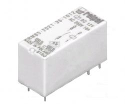
    If you ignore the warranty, can you easily replace the relay in INT-ORS using a soldering iron? What relays are installed there?
    What will be better INT-ORS / IORS or INT-O and separate 12VDC / 230VAC 16A relays on rail sockets? The price of the relay and the socket is PLN 20-30, but it is easy to replace. I am also considering INT-ORS and additional relays only for riskier circuits.
    I'm going to control:
    - 230V LED lighting, simultaneously on one circuit, up to 20 IKEA 5-7W lamps with sin fi 0.6-0.9 and each with its own impulse power supply,
    - dehumidifier with a few hundred W motor - here will be an external relay,
    - heating devices - external relays / contactors,

    It turns out that I can't use the built-in ORS relays too much and I don't need as many as eight outputs yet. So INT-O and external relays will be cheaper. It is easier to place the relay next to the device and pull the control cable than to multiply the number of circuits connected to the switchgear.
    ORS, on the other hand, is a neat solution with additional controls that will show the current status of your devices.

    If I knew what relay is inside it would make it easier to decide what to choose.
    What are INT-ORS suitable for in terms of load capacity, and what is it better to use external ones?
  • ADVERTISEMENT
  • #3 16533761
    Jan_Werbinski
    Level 33  
    I'm testing the Integra. I do not know how many outputs will be left, because the project is undergoing modifications. Probably four.
    Probably it would be enough to control relays, but I know myself and anticipate improvements and constant modifications. That's why I prefer the expansion module right away.
  • #5 16534477
    Jan_Werbinski
    Level 33  
    I also decided on INT-O, but a fellow installer says that INT-ORS is better because it is neat and helps to keep the cabling in order and it has never had a failure.
    The opposite opinion here in the forum - that it is better to separate relays because of the ease of replacement.
  • #6 16534716
    sosarek

    Level 43  
    You can safely use INT-O if you care about the possibility of replacing / matching relays for specific applications.
    As for the cabling - if you do it wisely, you'll always have order :)
    Helpful post? Buy me a coffee.
  • #7 16920301
    dkoruba
    Level 7  
    This topic will warm up a bit, but I am also wondering how to better solve the issue of relays. It also seems to me that it is better to buy INT-O and separately relays for the DIN rail.

    Can you recommend any specific 230 V relays?
    I wanted to use them to control LED lighting outside the house.
    In addition, for controlling a hot water circulation pump.

    I currently have a Satel Integra 32, but I probably regret not buying a larger switchboard, e.g. 64 or 128 at once ...
    The only problem I have is that it will be an installation in an existing home, so it's hard to route cables anywhere.
  • ADVERTISEMENT
  • #8 16920379
    bhtom
    Level 38  
    Hello,

    dkoruba wrote:
    I currently have Satel Integra 32 ...


    Who advised my colleague such a choice? Does your colleague have an additional buffer power supply in his system?

    Best regards.
  • #9 16920543
    dkoruba
    Level 7  
    Well, it was recommended to me by one vendor from one alarm company ... "You'll be pleased"

    As for the additional buffer power supply, I have only one power supply in the housing.

    I am a layman when it comes to alarms, I was able to successfully install and connect the detectors, connect them to the control panel, connect the ETHM-1 Plus module, pre-program it via the USB / RS cable and then remotely via ETHM-1 Plus with the DLoadX program.
  • ADVERTISEMENT
  • #10 16920745
    bhtom
    Level 38  
    Hello,

    dkoruba wrote:
    I am a layman when it comes to alarms


    dkoruba wrote:
    I was successful ...


    Buddy, just satisfaction is not enough, although it's still a lot. I suggest starting all over again and calculating the current balance of the entire system.

    dkoruba wrote:
    As for the additional buffer power supply, I have only one power supply in the housing.


    I understand that you are writing about the power supply on the control panel board ... Remember, however, that Integra 32 has only a 1.2 A power supply, which in your case (additional expanders, external relays) may not be enough ...

    Best regards.
  • ADVERTISEMENT
  • #11 16923234
    dkoruba
    Level 7  
    Currently connected to the system:
    Subassembly name Quantity Power consumption Total current consumption
    INTEGRA 32 1 piece 127 - 234 mA 234 mA
    PIR Pyronix KX 15DD 5 pcs 11 - 12mA 60 mA
    Pyronix KX 15DT 2 pcs 24 - 30 mA 60 mA
    Ethm-1 Plus 1 piece 70 - 80 mA 80 mA
    GPRS-T4 1 piece 45 - 190 mA 190 mA
    INT-O 2 pcs 30 - 160 mA 320 mA
    INT-E 2 pcs 35 - 80 mA 160 mA
    INT-KLCDR-BL 1 piece 60 - 156 mA 156 mA


    In total, it is about 1260 mA.
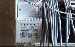
    The transformer is as in the picture: 18V / 2A Satel INT-O, INT-ORS & INT-IORS: Comparing Relay Performance, Replacements & 230V LED ControlTransform..or.png Download (125.96 kB)

    The power supply will probably be insufficient if you want to connect more output expanders. But I don't know if I need relay outputs, if separate relays can be controlled with a small current.
  • #12 16923276
    bhtom
    Level 38  
    Hello,

    What about the battery charging current?
    There are no signaling devices in the system?
    You can see that there is not enough already , and the expenditure of trafo has nothing to do with the expenditure of the power supply on the board.

    Best regards.
  • #13 16923316
    dkoruba
    Level 7  
    So what power supply would I have to buy to be sufficient for the needs of such a system? I plan to add a few more detectors and a few reed switches.

    Unfortunately, during the construction of the house, I ignored the topic of alarm and home automation and now I suffer unmerciful torture, because it is impossible to let the cables go in some places ...
    In addition, those who did this alarm to me were a bit of a maniana ...
  • #15 16927947
    Konrad Kl.
    Level 14  
    You should start with calculating the current balance according to the appropriate formula.
  • #16 16928589
    szydas
    Level 12  
    dkoruba wrote:
    So what power supply would I have to buy to be sufficient for the needs of such a system? I plan to add a few more detectors and a few reed switches.

    Download the ConfX program from Satellite and upload everything you have and what you plan to it, you can use the sample base (building design) because it does not matter yet where the detectors are. The program will calculate your electricity needs and you will be able to choose a power supply.
    Quote:

    Unfortunately, during the construction of the house, I ignored the topic of alarm and home automation and now I suffer unmerciful torture, because it is impossible to let the cables go in some places ...
    In addition, those who did this alarm to me were a bit of a maniana ...

    Well, welcome to the club. Now I am also changing CA-10 ("Sir, until the end of your life, you only need to overpay") to Integra 64 and combine with automation (Zamel Exta free) and Abax, because I'm not going to unfold the furniture and hammer the walls.
  • #17 19750662
    skrzyniarz1987
    Level 5  
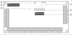
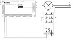
    The shelter has a satellite perfecta 16 alarm control panel and I want to expand it with an INT-O output expander to control external lighting and central closing and opening of all roller shutters. For this, using relays with a 12V coil and a 230V load. Would anyone tell me what the connection diagram looks like on the side? Satel INT-O, INT-ORS & INT-IORS: Comparing Relay Performance, Replacements & 230V LED Control INT-O expander to activate the low-voltage relay? Thank you for your help Satel INT-O, INT-ORS & INT-IORS: Comparing Relay Performance, Replacements & 230V LED Control
  • #18 19750943
    bhtom
    Level 38  
    Hello,

    Maybe some initiative from my colleague and some own diagram to check? And not like waiting for a ready ... ;)

    skrzyniarz1987 wrote:
    I have a satellite perfecta 16 alarm control panel and I want to expand it


    Will the control panel power supply withstand such an expansion?

    Regards.
  • #19 19751822
    skrzyniarz1987
    Level 5  
    I wrote down the INT-O Expander connection. movement, siren, 10 reed switches, and INT-E Expander .... And I want to add this INT-O Expander ... Satel INT-O, INT-ORS & INT-IORS: Comparing Relay Performance, Replacements & 230V LED Control
  • #20 19752582
    bhtom
    Level 38  
    Hello,

    skrzyniarz1987 wrote:
    I have scheduled the connection of the INT-O Expander


    This is how they feel completely ...

    skrzyniarz1987 wrote:
    if the diagram is correct


    No, it's not.

    skrzyniarz1987 wrote:
    what can be used for the low voltage OC-1 outputs which are located on the left side of the expander


    They can be used to actuate external relays, provided, of course, that the current consumption of the relay coil does not exceed the maximum load capacity of the OC output.

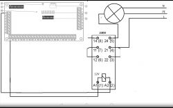
    I advise you to read how the relay works, because even the lighting circuit is connected incorrectly. It was on the forum. The relay above has two independent switching paths, and you connected the L phase to one path and the output to the other ...
    Additionally, you have connected the relay coil directly to the expander relay output. There is no tension there, it's just a contact. See the datasheet of your relay, check the coil current, if it is less than 50 mA, use the expander OC outputs directly. Why is the relay supposed to control the relay ...

    Regards.
  • #21 19753373
    skrzyniarz1987
    Level 5  
    In fact, the relay for lighting the 2nd half, I improved, although the connection of the power supply of the low-voltage coil itself is still rather bad, where this Expander will give 12V and where are the com which I need to drive the relay? Satel INT-O, INT-ORS & INT-IORS: Comparing Relay Performance, Replacements & 230V LED Control
  • #22 19754664
    bhtom
    Level 38  
    Hello,

    skrzyniarz1987 wrote:
    The expander will provide 12V voltage and where are the com which I need to drive the relay?


    Read how the OC outputs work, for example in the control panel (it is similar in the module). You have one potential at the OC output, and the other is supplied from the power supply that powers the module.

    skrzyniarz1987 wrote:
    Actually a relay for lighting the 2nd half


    You can connect these "2 halves" in parallel, thus increasing the load capacity of the switching contact. As for the relay itself - I suggest choosing one in a transparent housing, mounted, of course, in a socket on a DIN rail. It will be possible to easily check the degree of burnout of the contacts and possibly replace the relay in case of damage.

    Regards.
  • #23 19756365
    skrzyniarz1987
    Level 5  
    bhtom thank you for your help
    In that case, I understand the 12V / 230V relay to its low voltage DC coil I connect the OC-1 as a ground and control it, and 12V on the other side of the coil for permanent power supply, e.g. from the alarm control panel, e.g. AUX ... Be from a separate power supply only if I would use (plus) from an additional power supply, what to do with its - (minus)? Or by connecting a second dedicated power supply to this expander ...
  • #24 19756414
    bhtom
    Level 38  
    Hello,

    All power supply COMs must be connected to each other.

    skrzyniarz1987 wrote:
    Be from a separate power supply


    Just remember that it should be a buffer power supply.

    Greetings.
  • #25 19756431
    skrzyniarz1987
    Level 5  
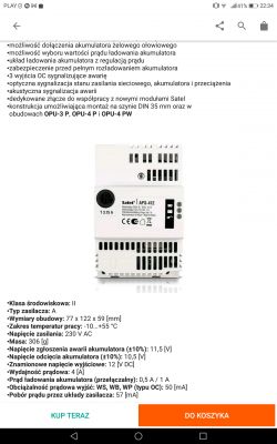
    I will order the same one that powers the alarm control panel and connect it directly to the INT-O expander socket and I will recommend it ( 12V) to the relay coil output for lighting ... 50mA ... How do you convert mW to mA?
    Satel INT-O, INT-ORS & INT-IORS: Comparing Relay Performance, Replacements & 230V LED Control
  • #26 19756433
    bhtom
    Level 38  
    Hello,

    I see you completely don't understand what to do ...
    There is a transformer in the photo and this is not a power supply ...

    Greetings.
  • #27 19756437
    skrzyniarz1987
    Level 5  
    I read too much information, somewhere I read that to power the control panel and Expanders you need to use the same power supplies ... I already know what to use, I think it will work
    Satel INT-O, INT-ORS & INT-IORS: Comparing Relay Performance, Replacements & 230V LED Control

    Added after 4 [minutes]:

    12 V from the buffer power supply gives to the relay coil, while the minus from the buffer power supply to which socket (com) is best to connect in Expanders or is it a difference to the control panel?
  • #28 19756518
    bhtom
    Level 38  
    Hello,

    skrzyniarz1987 wrote:
    I already know what to use, I think it will work


    Remember about the battery for this adapter.

    skrzyniarz1987 wrote:
    minus from the buffer power supply to which socket (com) is best connected to the Expander noun is there any difference to the control panel?


    There is no difference. Of course, the COM of the control panel and the expander is also to be connected, but it's probably clear ...

    Calculate the maximum power consumption of devices in your system, because it may turn out that an additional power supply will not be necessary.

    Greetings.

Topic summary

The discussion centers around the performance and replacement options for Satel's INT-O, INT-ORS, and INT-IORS relay modules, particularly in relation to their suitability for controlling high-power devices like 230V LED lighting and dehumidifiers. Users express concerns about the INT-ORS relays sticking together under high starting loads and the feasibility of replacing them with soldering. The consensus leans towards using INT-O with separate 12VDC/230VAC relays for easier replacement and better adaptability for specific applications. Recommendations include using DIN rail-mounted relays for external devices, and considerations for power supply adequacy are highlighted, especially for systems with multiple components. Users also discuss the importance of proper wiring and power management to ensure system reliability.
Summary generated by the language model.
ADVERTISEMENT