Welcome to the esteemed group. 🙂
I am about to have my electrics laid out. I'm delving into the subject of home automation, as I'd like to be able to control the roller shutters and lighting at my home from the control panel (via an expander) as well as from traditional switches.
Searching the internet for wiring diagrams, the ones described by pik_1 on this forum seem interesting.
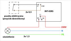
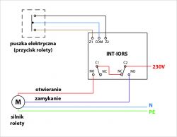
Light and roller shutter control - INT-ORS satellite expander .
The control of the roller shutters is clear to me. However, I have a question regarding the lighting scheme. I have the impression that the presented scheme prevents the simultaneous use of traditional switches and the INT-ORS expander. Let's assume that I am activating bulb C1 via the Expander - can I now switch it off via a traditional switch? In my opinion, no.
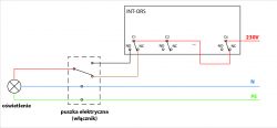
Below is a diagram I have drawn. In general, nothing revealing - an application of a stair switch diagram so to speak.
A 3x1.5 cable from the bulb to the box and a 4x1.5 cable from the box to the expander. Terminals C1, C2,.... are connected directly to voltage, unless you want to dedicate the last terminal Cx to switching off all the lighting (as in the attached diagram).
 .
.
What do you think of this solution? Is it optimal or can you think of something better?
PS. One more question - maybe someone knows: with the application installed (from Satel) on a smartphone, is it possible to read whether the bulb is on or off? I guess that having INT-ORS expanders we can only see the position of the individual relay (whether it is in NO or NC position), and since the bulb can be on at both NO and NC (depending on the position of the traditional switch) we don't have that possibility?
I would appreciate your opinions!
Greetings!
I am about to have my electrics laid out. I'm delving into the subject of home automation, as I'd like to be able to control the roller shutters and lighting at my home from the control panel (via an expander) as well as from traditional switches.
Searching the internet for wiring diagrams, the ones described by pik_1 on this forum seem interesting.
Light and roller shutter control - INT-ORS satellite expander .
The control of the roller shutters is clear to me. However, I have a question regarding the lighting scheme. I have the impression that the presented scheme prevents the simultaneous use of traditional switches and the INT-ORS expander. Let's assume that I am activating bulb C1 via the Expander - can I now switch it off via a traditional switch? In my opinion, no.
Below is a diagram I have drawn. In general, nothing revealing - an application of a stair switch diagram so to speak.
A 3x1.5 cable from the bulb to the box and a 4x1.5 cable from the box to the expander. Terminals C1, C2,.... are connected directly to voltage, unless you want to dedicate the last terminal Cx to switching off all the lighting (as in the attached diagram).
 .
.
What do you think of this solution? Is it optimal or can you think of something better?
PS. One more question - maybe someone knows: with the application installed (from Satel) on a smartphone, is it possible to read whether the bulb is on or off? I guess that having INT-ORS expanders we can only see the position of the individual relay (whether it is in NO or NC position), and since the bulb can be on at both NO and NC (depending on the position of the traditional switch) we don't have that possibility?
I would appreciate your opinions!
Greetings!


