logo elektroda
logo elektroda
X
logo elektroda

Connecting 12V 3-Phase Voltage Regulator to Evinrude 60km Engine: Wire Order & Compatibility

cough 11883 9
ADVERTISEMENT
Treść została przetłumaczona polish » english Zobacz oryginalną wersję tematu
  • #1 16539726
    cough
    Level 9  
    Hello, I have an evinrude outboard engine 60km, in which the voltage regulator fell, getting the original hard and if it could be a price between 200-300 PLN. The original controller has 4 wires, yellow, yellow-gray, yellow-blue, and red, the weight is from the housing. 3 yellow cables come out from under the magnet that match the colors. On the Allegro I found a regulator from Honda which has 5 wires, red 3 yellow and black, we know black ground, red battery output and 3 yellow connected to the coils. the question is, do the yellow wires need to be connected in any order or is it neutral?
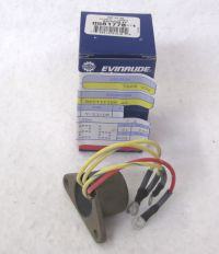
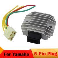
    Connecting 12V 3-Phase Voltage Regulator to Evinrude 60km Engine: Wire Order & Compatibility

    Connecting 12V 3-Phase Voltage Regulator to Evinrude 60km Engine: Wire Order & Compatibility
  • ADVERTISEMENT
  • Helpful post
    #2 16539767
    piotrekwoj1
    Level 42  
    No matter how you connect.
  • ADVERTISEMENT
  • #3 16540993
    BANANvanDYK
    Level 42  
    Well, I would not necessarily suggest here that the alternator and regulator are three-phase factory. The original regulator is quite small. Three different colors of wires may also suggest something. Looking at the diagrams of old models, these were not very typical solutions. You should look at the schematic or servicing of this model.
    The price of PLN 200-300 is about the same as the original three-phase motorcycle regulator. Chinese fakes for PLN 100 should not be trusted.
  • ADVERTISEMENT
  • #4 16541305
    cough
    Level 9  
    Hello, today I installed a motorcycle regulator, and the matter is that during operation the voltage in the installation is about 12.6V, a bit low on my eye. After disconnecting the output from the controller and measuring how much the controller gives at the output, the controller not connected to the installation gives, depending on the RPM, 13.7-14.1V, i.e. as it should be. The question is what happens when I connect the controller output to the installation where the battery is, the voltage is not as high as when disconnecting the controller.
  • #5 16544994
    BANANvanDYK
    Level 42  
    You would need to measure the actual charging current, or connect a fully charged battery to reach 14.4V quickly. Motorcycle regulators must not be disconnected from the battery during operation, measuring the voltage at the output does not make sense. But as I wrote earlier, you need to look at the service center on the construction of the charging system.
  • #6 16545142
    cough
    Level 9  
    it will be hard to get a service, the most puzzling is the fact that when the system is disconnected, the regulator gives the right voltage, while when it is connected to the battery, the voltage on the whole line + is as much as the battery. do you propose to put some ammeter in line?
  • #7 16546750
    cough
    Level 9  
    is it possible that the regulator can see battery voltage at 12.5v and cut off charging? I made a test to the output from the regulator, I connected the halogen and the meter was plugged in, after starting the engine, the halogen began to glow on the meter was about 1.1A with increasing the revs on the meter came to 3A. the turnover was at the level of 1.500 also the regulator looks 100% functional only why if it is connected to the battery, the voltage in the installation does not increase and the power supply is at the level of 0.5A
  • #8 16546767
    piotrekwoj1
    Level 42  
    Electricity and what was the voltage at that time?
  • ADVERTISEMENT
  • #9 16548978
    BANANvanDYK
    Level 42  
    K *, how many times do you have to explain that a three-phase motorcycle regulator cannot work without a battery ?! First of all, the output voltage is then incorrect - in a motorcycle it can damage electronics (ECU, TCI / DC-CDI modules, counters). In addition, it may damage the controller.
    The regulator is to be connected with a battery. The measurement of the charging current is best done with a clamp meter with the function of measuring direct current. In a worse case, you can use an ammeter with a range of up to 30A, preferably by connecting a shunt to the system. The ammeter has the disadvantage that a voltage drop leads to a change in the charging voltage.
    And as I wrote earlier, and I repeat it for the third time, you should check what the alternator system is. Nobody means three alternator phases with a different cable color, because the phase order etc. is completely irrelevant. Standard three-phase alternator terminals are three yellow wires, or sometimes three white wires.
  • Helpful post
    #10 16549065
    kwok
    Level 40  
    What is the generator's capacity?
    What voltage on generator cables without a regulator connected?
    What battery capacity?
    Specify the engine type exactly.
    Old solutions were slightly different. Starting from the simplest bridge rectifier through series regulators to today's solutions. Here, I think there should be a serial regulator (the more current you take, the more it warms up) and the one you bought works exactly the opposite - I don't want to explain why.

    Added after 11 [minutes]:
    L
    On eBay for 15-30 bucks, stimulants for 5 - why do you carve?

    I used a similar split and it turned out that it is only a bridge and the magnet's performance is a few amps.

    Added after 35 [minutes]:

    After analyzing the diagrams, I find that it is only a bridge, the rest of the package is written RECTIFIER and not a rectifier voltage regulator or voltage regulator.
    http://yuichan.org/detail/wiring-diagram-1997-50-hp-evinrude.html

Topic summary

The discussion revolves around connecting a 12V 3-phase voltage regulator to an Evinrude 60km outboard engine. The original regulator has four wires (yellow, yellow-gray, yellow-blue, and red), while a potential replacement from Honda has five wires (three yellow, red, and black). Users debate the necessity of connecting the yellow wires in a specific order, with some asserting that the connection is neutral. Concerns arise regarding the regulator's performance, as measurements indicate low voltage output when connected to the battery, despite proper output when disconnected. Recommendations include ensuring the regulator is connected to a battery during operation and measuring charging current accurately. The discussion highlights the importance of understanding the alternator system and the potential risks of using incorrect regulators.
Summary generated by the language model.
ADVERTISEMENT