


logo elektroda
logo elektroda
X
logo elektroda

Ducati Energia Regulator Connection: 4-Pin Setup, Stator Cable, Ground, Battery - User's Experience

Fallschirmjager44 16245 9
Best answers LABEL_AI_GENERATED

How do I wire a Ducati Energia 4-pin regulator on a Simson S51 LFK so it charges the battery instead of feeding AC?

This regulator is described as a lighting voltage limiter from Yamaha DT 50 / MBK / Malaguti, with two pins for the lighting circuit and two pins for ground, so it is not wired like a universal battery charger/rectifier [#16587640] It is also noted to be similar to the Ducati Energia 3-pin cube used on some AM6 bikes, which suggests the pinout is not the one you assumed [#16587640] The thread adds that there are two different ways to connect such controllers, so you need the exact regulator variant or its pinout before wiring it in [#16603096]
AI summary based on the discussion. May contain errors.
ADVERTISEMENT
Treść została przetłumaczona polish » english Zobacz oryginalną wersję tematu
  • Questioning Ducati regulator pin continuity and wiring setup

    #1 16586596
    Fallschirmjager44
    Level 9  
    Posts: 5
    Rate: 12
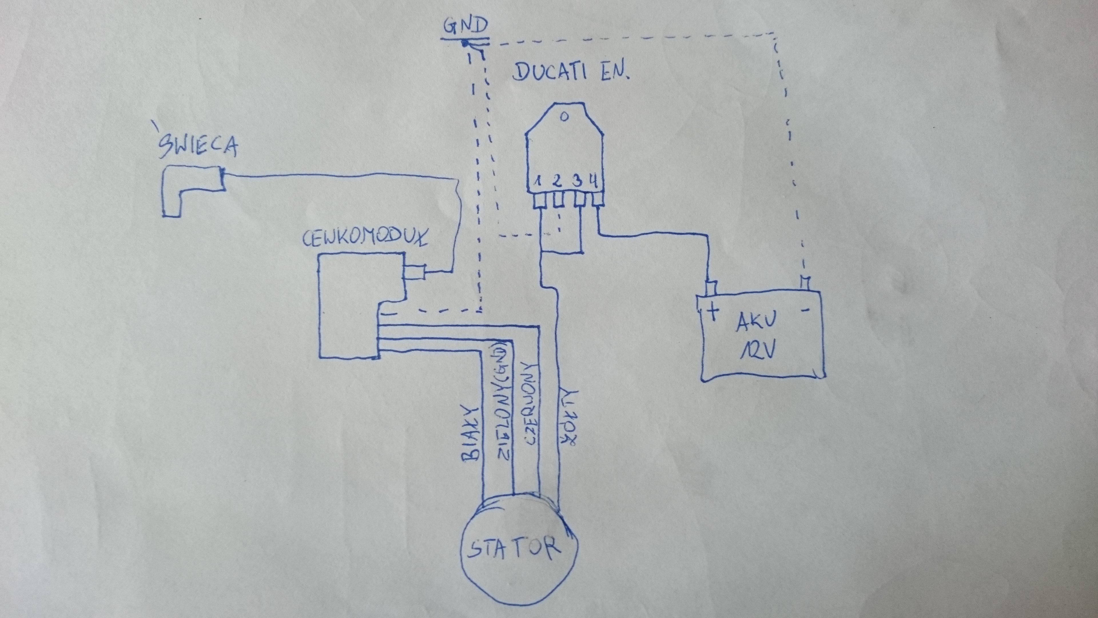
    Hello colleagues. Well, I bought a Ducati regulator and I connect it nicely according to the recommendations found on the internet and the zonk does not work. It is a 4-pin regulator in an alu housing. I connect it this way, the regulator having the pins connected to each other, of course, starting from the left, 1 pin - yellow cable from the stator, i.e. charging and lights, gives ground to the second pin, to the third pin it gives a bridge from the first pin and theoretically it should go on the fourth plus on the battery. I will add that when I checked the regulator pins with an ohmmeter, there is a transition between pin 1 and pin 2 and the same applies to pin 3 and pin 4, is the transition okay between them? When I start the moto and check pin 4, there is some residual voltage there, of course, the rest of the installation was disconnected for the duration of the test. I don't know what's going on and I don't want to experiment too much to not burn anything. If anyone has an idea but knows the solution, be grateful.
    Moto is a simson s51, with lfk ignition.
  • ADVERTISEMENT
  • #2 16586622
    jack63
    Level 43  
    Posts: 11792
    Help: 851
    Rate: 2822
    Draw a diagram of your connections with a clear indication to which coil and how connected (or not) to ground.
    You don't know what you want to achieve, because you write:
    Fallschirmjager44 wrote:
    yellow cable from the stator, i.e. charging and lights,

    The yellow cable does not come out of the Simson's stator (generator) in the original.
  • ADVERTISEMENT
  • #3 16586625
    Fallschirmjager44
    Level 9  
    Posts: 5
    Rate: 12
    But I pointed out that the ignition is LFK. The yellow cable from the stator is the light and charging coil. And this is the only one I have at my disposal when it comes to charging and lights, the rest of the wires from the stator are for the coil module.
  • ADVERTISEMENT
  • #4 16586657
    jack63
    Level 43  
    Posts: 11792
    Help: 851
    Rate: 2822
    Fallschirmjager44 wrote:
    But I pointed out that the ignition is LFK.

    Ignition so what ??? It's about a generator.
    Give me more info about this lfk.
  • Need to wire rectified output to the battery

    #5 16586696
    Fallschirmjager44
    Level 9  
    Posts: 5
    Rate: 12
    I think it's better to focus on the regulator because the generator is ok. In Simson it was different originally and I know about it, and in this case we have such a system that a few coils are used for one and it is efficient enough to power the lights and charging, and it is a yellow cable. There is only one question how to connect this device so that the rectified current is fed to the battery, the previous owner had a yellow cable under the battery, i.e. the battery was receiving alternating current, and as you know, it should not be so. For this regulator I gave almost 7 dych and such a lame. I must admit that I get a bit frustrated. I would like to add that there are no markings on the regulator and the net all over the top ... even on the Ducati Energia website.
  • ADVERTISEMENT
  • #6 16586773
    jack63
    Level 43  
    Posts: 11792
    Help: 851
    Rate: 2822
    Instead of getting frustrated, give a diagram of what you have and how you connected.
  • #7 16587635
    Fallschirmjager44
    Level 9  
    Posts: 5
    Rate: 12
    Ducati Energia Regulator Connection: 4-Pin Setup, Stator Cable, Ground, Battery - User's Experience So fast, it looks like this
  • #8 16587640
    BANANvanDYK
    Level 43  
    Posts: 7818
    Help: 1167
    Rate: 2602
    This is a voltage regulator from Yamaha DT 50 and its twin MBK and Malaguti. The regulator has only a voltage limiter for lights, two pins from the lights (first - alternator, second - bulbs) and two pins from ground. In total, the connection is similar to the Ducati Energia 3-pin cube used in other AM6s, eg Aprilia RS 50.
    Jacek himself does not know what he is selling, as well as with voltage regulators from Longjii with a changed pinout, which did not want people to work.
  • #9 16603096
    tallellion
    Level 9  
    Posts: 22
    Rate: 23
    There are two different ways to connect such controllers
  • #10 16603100
    Fallschirmjager44
    Level 9  
    Posts: 5
    Rate: 12
    So please present what.

Topic summary

LABEL_AI_GENERATED
The discussion revolves around the connection issues faced by a user with a Ducati Energia 4-pin voltage regulator. The user describes their wiring setup, which includes a yellow cable from the stator intended for charging and lights, and expresses confusion over the regulator's functionality. Other participants request a wiring diagram and provide insights into the connections, noting that the regulator may be misidentified as a Yamaha DT 50 component. The conversation highlights the importance of correct wiring to ensure the regulator properly rectifies current to the battery, with frustrations expressed over the lack of clear markings on the regulator and the need for accurate connection methods.
AI summary based on the discussion. May contain errors.
ADVERTISEMENT