logo elektroda
logo elektroda
X
logo elektroda

Simson SR50 Magneto & Coils System Installation: Connecting 5 Cables for Spark Restoration

Kawa900r 13632 11
ADVERTISEMENT
Treść została przetłumaczona polish » english Zobacz oryginalną wersję tematu
  • #1 16585710
    Kawa900r
    Level 2  
    Hello, I know that the topic has been raised many times, however, in none of the threads, although they addressed my problem I did not find a solution.
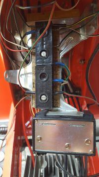
    Well, I have a Simson SR50 I mentioned "Magneto" and what is under it, that is the whole system of coils and the pulse generator or the magneto I do not know how it is determined. and after this exchange I do not have a spark, help me how to connect these 5 cables, the diagrams are black magic for me, the installation is unstretched regarding the cable.
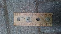
    I have decoded the symbols on the switchboard as colors, but the diagrams, e.g. "bolt" are drawn in series and I have 4 cross-shaped holes,
    can anyone help me i'm far from home with my sim because NL, I can't fix it for a long time ..... save. I add photos to the post, with the diagrams, for example, the colors of the cables do not rip me. It is important for me to have a spark ...
    Simson SR50 Magneto & Coils System Installation: Connecting 5 Cables for Spark Restoration
  • ADVERTISEMENT
  • Helpful post
    #2 16585743
    teskot
    Level 37  
    5 wires come out of the magnet: blue connects to the ignition module terminal 3, red connects to module terminal 14; terminal 31 of the module with a brown wire to the scooter ground, terminal 15 of the module with contact 15 of the ignition coil, and the other coil terminal to ground. Pin 2 of the module with a brown and white wire to the ignition switch. You already have a spark and putting out the engine. Now red and white with a magnet with the same ignition. You already have a headlight. Red-yellow and red-gray for a bridge rectifier under terminals marked "~"; "-" ground bridge, "+" to terminal 59 of the controller. Terminal 31 of the regulator for ground, 49a with a gray-black wire to the indicator lamp switch, and 49 with a black wire to terminal 15 of the ignition switch. While the ignition 30 terminal (red-green wire) is connected to the battery, you already have charging. You probably can handle the lights. If you don't write it.
  • ADVERTISEMENT
  • Helpful post
    #3 16586079
    BANANvanDYK
    Level 42  
    Is it SR50 C or SR 50/1? Because I don't like certain things. Is this the export version or the normal East German version?
    After replacing the stator for a new one, unfortunately I will disappoint you. The new power coils are not made according to the original and are the reason for burning ignition modules, and I still see the original DDR. I have now seen that the original DDR or BRD power coils are available but at a price comparable with the entire DDR stator "from old stock".
  • #4 16587696
    Kawa900r
    Level 2  
    I bought it from a German, three hundred kilometers from the Netherlands, from the very beginning I have a problem with electricity here, all 12V bulbs, so a 12V installation would seem but I have, for example, a 6V bottle coil? I will make some extra photos and throw them in, help me because I will get my head with this bike.
  • Helpful post
    #5 16587782
    teskot
    Level 37  
    The coil is always 6V, regardless of the voltage of the rest of the installation. I wrote you what and how to connect so what's the problem? I hope you know that these 2 connectors have different contact layouts? Some are joined in pairs and some in fours.
  • ADVERTISEMENT
  • #6 16588619
    BANANvanDYK
    Level 42  
    In electronics, a 6V bottle coil, in a platinum plate a 12V bottle coil, always.
    A valuable note with these connectors, because those fitted have a general marking, which does not specify the way of distribution of single and double connectors.
    The cable cable shows that this is the SR50 / 1B version, so both connectors should have 3x double terminal blocks (middle and ends) and 2x single terminal blocks. Only that in SR50 / 1B there was generally no electronics - it appeared only in 1995 but in the Halogen version, so with the EWR system instead of the Graetz bridge, as in the SR50 / 1C. The ignition of the electronics may have been added by the previous owner.
    The second thing that I see there are two thick wires (0.75 mm?) ;) and these were used in old SR50 with 6V / 12V installation.
  • ADVERTISEMENT
  • #7 16588627
    teskot
    Level 37  
    BANANvanDYK, I'm not going to undermine your speech, but 4 floors below is my SR50 not combined from 1988 and has CDI ignition.
  • #8 16588640
    BANANvanDYK
    Level 42  
    From 1986 there were SRki with electronic ignition and 12V installation, only the first series were SR50C and SR50CE with Bilux light, old thick installation and round lamps. Since 1989, there were SR50 / 1C and SR50 / 1CE versions that already had Halogen lighting, a new installation on thin wires and rectangular lamps.
    Platinum planners were 1988 until 1988, 12V since version B.
  • #9 16588845
    Kawa900r
    Level 2  
    hey i took off these black cubes under them the description of this distribution is as in the picture, Simson SR50 Magneto & Coils System Installation: Connecting 5 Cables for Spark Restoration

    Added after 1 [minutes]:

    I will take more photos because I can see that people have an idea here, I didn't even know that there were so many versions of Simons, for me there were 3 :P enduro, ordinary and scooter :)
  • #10 16589381
    teskot
    Level 37  
    Then you have the set. Color coding of the wires in the diagram. ro Rot or red; ge is GELB or yellow, b is Blau or blue, sw is Schwarz or black, gn is grun or green, br is brown (i.e. mass, minus the Germans
    ).
  • #11 16589392
    Kawa900r
    Level 2  
    Teskot, I'm limiting me more but I can't get a white-red cable from under the magnet, and do I need to have the back connected to this whole switchboard to have a spark to fire :)
  • #12 16590210
    BANANvanDYK
    Level 42  
    What wire colors come from this non-original stator? BTW. since you were replacing the magnetic wheel, is it for electronics (cutouts in pole pieces)? Do you have the original ignition from him?

Topic summary

The discussion revolves around the installation of the magneto and coils system in a Simson SR50 scooter, specifically addressing the connection of five cables to restore spark functionality. The user expresses difficulty in interpreting wiring diagrams and seeks assistance in correctly connecting the cables. Responses provide detailed wiring instructions, including color codes for connections to the ignition module and ground. There is also mention of variations in models (SR50 C, SR50/1) and the impact of using non-original stators on ignition performance. The importance of matching the correct voltage for components, such as the 6V coil, is emphasized, along with the need for proper connections to achieve spark ignition.
Summary generated by the language model.
ADVERTISEMENT