logo elektroda
logo elektroda
X
logo elektroda

FAAC 740 Drive: Magnetic Limit Switch Unresponsive, Reed Switch & Sensor Testing

jarmiel 14973 15
ADVERTISEMENT
Treść została przetłumaczona polish » english Zobacz oryginalną wersję tematu
  • #1 16601326
    jarmiel
    Level 2  
    Hello
    I have a FAAC740 drive with magnetic sensors, a photocell and a remote control. The drive has been operating for two years, but recently at
    closing, it stops responding to the magnetic limit switch - it reaches a post and a beech. You have to stop it with a remote control.

    I read some of the posts and it seemed the problem was with the reed switch or the magnets.
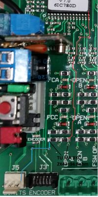
    During the tests, I noticed that the FCC LED goes out when opening, but the FCA does not go out when closing.
    However, after dismantling and disconnecting the sensor (J5) and checking it with a meter, it turns out that everything is OK: one contact reacts to one magnet, the other to the other. However, when the reed switch is connected to the drive, only the FCC LED goes out and the FCA does not react.

    However, I noticed that after removing the reed switch from connector J5, both LEDs are on - should they not go out then?
    When I short the middle pin with one of the extreme pins, the FCC goes out, but when I short the middle pin with the other FCA pin, it still lights.
    The tile is clean and dry. Logic set to EP, I checked the settings - everything seems to be OK.
    The gate also works without any problem.

    Does anyone have an idea what could be the reason?
  • ADVERTISEMENT
  • #2 16601378
    kotbury
    Gantry automation specialist
    The board can be clean and dry, but remove the terminal block and remove the green plastic from the pins. Very often, under this green stand, the tracks corrode and get short circuits or interruptions (if there is a connection - patch it, and to be sure, correct the February pins) - and the drive behavior indicates a break.
    If nothing else - follow the whole way from the FCA terminal to the Prock leg - and check especially the condition of the resistors R46, R47 and R48 (all 47kOhm).
    There is a schematic for 740 on the forum - look for it.

    Quote:
    However, I noticed that after removing the reed switch from connector J5, both LEDs are on - should they not go out then?

    No - the active input is shorted to ground and as you wrote in the next sentence - the LEDs should be on in the free state (without the magnet - the gate in the middle - similarly with a disconnected switch) and go out when the appropriate magnet is brought closer - or the corresponding pin is shorted to ground, i.e. to the middle leg of the connector. If it does not go out - indicates a break from the FCA entrance somewhere on the way to the prock (or damage to the prock entrance itself - rare but possible).
  • ADVERTISEMENT
  • #3 16602044
    jarmiel
    Level 2  
    I removed the plate and looked at it - everything is clean, fresh, also under the plastic of the connectors.
    So I measured the path from FCA to the CPU and got stupid:
    first, the resistors are 32k each, although 473 are described, i.e. 47k according to the diagram.
    second: the resistance between points TP41 and TP40 is 36k and yet it should be a sum, i.e. about 65k
    it is similar on the FCC line: each of the R40 and R41 resistors is about 34k, but between the TP35 and TP34 points I measure 42k
    And there is 32k between FCA and FCC inputs.
    Resistance between pins of connector J5: extreme left to middle: 11k, extreme right-middle 22k.
    Board measured on a table without power and all connectors disconnected.

    And now the best:
    I decided to check how the drive will react when I change the sensor operation by inverting the J5 plug (possible after removing the plastic on the connector).
    But first, I connected everything normally and ... it goes!
    Although the FCA LED still does not go out, when the end magnet on the gate is approaching the code changes from 06 to 00 and the gate politely stops.

    For now, I have no idea what this could be about. But because the drive works, I leave it as it is until some insight or suggestion from someone else's side.

    Thank you for your help, but if anyone else has an idea, please.

    greetings
    Jarek

    PS I could not find a schematic diagram on the forum, but I found it on the network - maybe someone will need it, so I am enclosing it.
  • #4 16603975
    kotbury
    Gantry automation specialist
    As for resistance measurements - measuring the soldered resistors gives strange values because apart from them, other things are also attached from the outside - for example, there is a stabilizer between the ground and the 24V plus, which probably shows some resistance, on the other hand there is a proccess that will probably show something on the ohmmeter and that everything is connected in parallel ...
    In fact, for the measurements, you would have to cut off the entire diode-resistor input circuit from power, ground and prock and then measure.
    It's probably easier on TP 40 and 42 to measure the voltage to ground when shorted to ground (it should be at the digital 0 level, i.e. below 0.8 V), and in the unconnected state - digital one (above 2.4V).
    As for the lighting of the diodes on the disconnected limit switch - in fact (I wrote incorrectly earlier) they should not light up (maybe there is some leakage after all - for peace of mind, I would rinse the input circuits with IPA or spirt and soldered everything). They should work as NC, that is, the attached limit switch in the passive state shortens FCA and FCC to ground, and only the magnetic run-on opens the appropriate direction (the same as NC STOP and EDGE inputs work - short circuit to ground - passive state - LED is on, open - active state, LED goes out). Check it manually - short-circuit both switches of the limit switch to ground, the gate moving in the given direction, when opened from the ground of the pin, of the respective switches, should stop.
    However, I would bet on a damaged magnetic limit switch - a classic problem in the 741.
  • #5 16604157
    jarmiel
    Level 2  
    I also believe these strange results are due to in-circuit measurement.

    As for the sensor - I hoped it was it, but as I wrote - I removed it and checked the response to the magnets.
    Each of the contacts reacts to only one pole (different for each one). And it's repeatable.
    In this situation, I do not really want to spend PLN 100 on a new sensor.

    I also did a test consisting in shorting the external pins in J5 to the middle pin (i.e. to ground).
    And one of them reacts by lighting the diode and closing the other one does not have such an effect. This suggests to me that, unfortunately, the problem is somewhere on the board.

    For now, I have to leave for a few days, but after returning, I plan to desolder a few elements so as to separate this circuit from 24V.
    If the problem persists, it will be affected by CPU inputs - and that would be a bad option.

    greetings
    Jarek
  • ADVERTISEMENT
  • #6 17001375
    sumar_84
    Level 11  
    Hello,
    I have a similar problem - no reaction to the limit switch when closing (the drive does not stop). The FCC diode goes out so I exclude the reed switch. Maybe something with a relay?
  • #7 17001746
    kotbury
    Gantry automation specialist
    Maybe a relay, and for now check the condition of the board under the limit switch connector and the circuit leading from the limit switch pins above for moisture, tar and corrosion (the LED is connected to the input - you can say - for a short time, only through passive elements - without the use of digital circuits and not necessarily will correctly map the input state). To be sure, check the voltage on the 14th pin of the processor - (or on the test point 34 - the control unit diagram is on the electrode) - when the limit switch is closed (i.e. on the LED - the gate status during movement) it should be 0V, and when closed - high - i.e. above 2 -2.5V.
    As if a relay - there is RL2 from the direction, and it is controlled by the T6 transistor (BC817 SMD)

    Quote:
    The FCC diode goes out so I exclude the reed switch

    Do not exclude so quickly and nevertheless check manually - on the closing gate, remove the limit switch plug (the input is NC - closed at rest) - the gate should stop.

    PS - in this drive the reed switches operate atypically - the sensor has built-in small magnets supporting the reed switches and the magnets on the toothed bar, when approached, cancel the magnetic field of the reed switch and the reed switch opens - it works "in reverse" (NC).
    Thanks to this, it is also possible to identify which magnet reaches the sensor.
    But hence (I suspect) the constant failures of magnetic sensors - reed switches when closed permanently for a few years like to stick together, and after these few years, poor quality magnets like to weaken.
  • #8 17001857
    sumar_84
    Level 11  
    Hi,
    I assembled the drive myself almost 5 years ago. About a week ago, the gate started going crazy, i.e. the primary symptoms were that the gate opened with the remote control. When it reached the end, the limit switch turned it off and remained open, it was impossible to close it anymore, I had to close it by hand. So I went to work, I disassembled the plate, there was corrosion on the plate near the limit switch connector. I cleaned the plate thoroughly with IPA spray from Würth, checked the condition of paths, etc. according to the scheme and here and there I improved February rather well. I only damaged the LED from the encoder signaling, I had to heat up a little at this point because the path was corroded, I have to buy a new one and solder it, but this probably does not affect the operation of the control itself, moreover, in advanced programming I have this EC option turned off. I additionally cleaned the entire PCB and sprinkled it with plastic spray for printed circuits. After putting it in the drive and setting the factory parameters, everything returned to normal, but without turning off the drive when closing :( , the limit switch, as I wrote earlier, passes the contactron, the FCC goes out and the gate continues and leaves the trolley .... I checked the relays on the board and the coil on both shows 1.4 KOhm. I do not know how the contacts behave, I will not check until next Saturday when I have time. The reed switch works on magnesium with the S and N poles. So far I set the gate operation time to 21 seconds, but it does not work well because it stays in a different position each time (I did not write EP logic is set so far).

    greetings
    Arthur


    ps. I will of course comply with the above information, I have to figure it out, because I feel sorry for 500 for a new album ...
  • #9 17002434
    kotbury
    Gantry automation specialist
    The relay may have a working coil and control, and the contacts are stuck, on the other hand, they are not relays - the drive stops opening - so the relay works, the gate moves when closing and opening - so the direction relay works too.

    Check - as I wrote earlier - the gate's reaction (not the LED) to manual closing and opening of the pins in the limit switch connector (the middle one is COM, the COMA short with the corresponding direction means the switch is at rest - i.e. with both pins shorted to the middle one, the gate should be able to go both ways side, opening one from COMa should simulate a working limit switch - and stop the gate moving towards the simulated limit switch).

    And check the transitions carefully - in the fig is marked in blue and red and the resistance (94 Kohm) is marked in black.

    FAAC 740 Drive: Magnetic Limit Switch Unresponsive, Reed Switch & Sensor Testing
  • #10 17003445
    sumar_84
    Level 11  
    I wrote as you wrote J5 and nothing, the same phenomenon, the transitions are checked ok. It turned out that there was no transition between the two 47 Kohm resistors. I corrected February and the meter showed 42 Kohm (not 2x47 as you wrote). As the next resistors at Open A and Open B showed the same, I decided to check the pd board with voltage.
    I connected the disc to the drive and it started to work.

    Conclusions:
    thin tracks, where there are soldered joints, will corrode over time and the tin will oxidize, these are such imperceptible cases that it is impossible to see. I cleaned the IPA after corrosion (white powder that precipitated, and what I noticed was that I improved the paths and connections of the components where I noticed corrosion. The connections between these two resistors I must admit that I did not check, just now, as you wrote to check the resistance there.
    When the closing magnet was brought closer, the FCC diode turned off and that confused me.

    Thanks so much for your help.
    I greet arthur
  • #11 17003949
    kotbury
    Gantry automation specialist
    Ok, good that it turned out.
    As for the resistors - I do not know what they are, but according to the diagram and on the photos from the net (I do not have a comparison on the original, I can see the drive only for a few days or hours, then it is already installed), both resistors have 47K, the lower value is read may result from the fact that it is connected to the rest of the circuit - e.g. there is a current loop through a chip with LED and a processor, both of which are connected to a common power supply ...
    But that's a detail.
    Quote:
    When the closing magnet was brought closer, the FCC diode turned off and that confused me.

    The LED was working because on the one hand it is powered (through the passive system) from 24V, and on the other, when the limit switch is shorted, it is massaged by 2 10K resistors connected with the contact of the limit switch to the ground - just before the said 2x47K resistors, and the break was just between them.
    In general, all input LEDs are similarly connected - and likewise completely independent of the prock. Prock's life is evidenced by a properly working display.

    As for invisible corrosion - there is one more (if what) place - paths under the green pin caps. In the case of strange drive behavior, the first move is to remove all overlays and check the situation under them.
  • ADVERTISEMENT
  • #12 20355581
    marnykn
    Level 6  
    Hello, this topic was started quite a long time ago but I suppose it's still valid. I, on the other hand, would like to ask about the limit switches, I see that in this case you wrote a lot about them. I have a Faac741 drive with magnetic limit switches and I would like to use these reed switches for the Satel alarm system. I need to know the state of the gate. I unhooked the J5 connector and, as you write, the gate on the middle pins (blue wire) and right pins (brown wire) opens. It is enough to move it slightly and we have a closed contact. However, when I plug the J5 connector into the motherboard, I always have a short circuit on two pins. The meter simply reads the state on the control panel and not on the reed switch. So just plugging in these contacts does nothing for me. I think right? The Proxima AKZ system remains, or another reed switch? Regards
  • #13 20355716
    kotbury
    Gantry automation specialist
    Yes, the control panel electronics falsify the resistance reading at the limit switch. The opposite situation (depending on the design of the alarm input circuit) is also possible - i.e. connecting the limit switch to the alarm will falsify its operation and interfere with the operation of the gate.

    I put on the AKZ twice and it works - with one contact it doubles the status of the limit switch for the control panel, with the other - isolated from both the limit switch and the control panel - it sets the limit switch status for other applications (and here there are even NO or NC contacts to choose from).
    You can also use a reed switch - and in order not to multiply the magnets - attach it somewhere near the original limit sensor (but with a distance so that the magnet built into the sensor does not short it) and use the same original end magnets of the drive.
  • #14 20355754
    marnykn
    Level 6  
    Thanks a lot, you cleared my doubts. I'll mess with the reed switch at the beginning, if it's too tight for a few magnets, I'll reach for the AKZ. Kind regards
  • #15 20506147
    dawidtrafny
    Level 11  
    Hello, I'm reviving an old topic.
    A small worm came in and made a short circuit at the back of the plate at the limit switch connector, which caused the drive rack to tear out the teeth on the bars ... the first and last because the limit switches did not work. Currently, after cleaning, the gate does not stop in the open position, it tries to go indefinitely until I press the button on the remote control. I suspect damage to the board, but ... the display works, the diodes from the limit switches work, the gate goes both ways, the intercom opens, etc.
    The question I have is ... Is it possible that the limit switch sensor was damaged by a short circuit caused by the snail?
  • #16 20506373
    kotbury
    Gantry automation specialist
    Quote:
    the gate goes both ways

    Unfortunately, there's something wrong with the album. If the limit switch sensor was damaged - the gate would only move in one direction (or not at all).
    And what do the FCA and FCC LEDs show when approaching a magnet sensor? Is one going out?
    You can take a test. Short-circuit all 3 pins of the limit switch sensor input (so that both FCA and FCC LEDs are on) and during movement, open the side pin so that the FCA LED goes out when opening and the FCC LED goes out - when the LED goes out, the drive should stop. This test is due to the fact that there is such damage to the limit switch detector or inputs on the board that, despite the proper operation of the FCA and FCC LEDs, the control panel does not catch any of the limit switches. Short-circuiting the input makes diagnosis easier. If such "improvisation" of limit switches does not work - the reason is deeper on the board.

Topic summary

The discussion revolves around troubleshooting a FAAC 740 drive experiencing issues with its magnetic limit switch, which has become unresponsive during closing operations. Users suggest checking for corrosion on the circuit board, particularly under the limit switch connector, and measuring resistances of associated components. The importance of verifying the functionality of the reed switch and ensuring proper connections is emphasized. Some users report successful repairs after cleaning corroded areas and correcting resistor values. Others discuss the potential for relay issues and the need for careful testing of the limit switch inputs. Additionally, there are inquiries about using the FAAC 741 drive's reed switches with alarm systems, highlighting compatibility concerns.
Summary generated by the language model.
ADVERTISEMENT