logo elektroda
logo elektroda
X
logo elektroda

Faac 740 Sliding Gate Actuator Issue: Gate Only Opens, Wiring and FSW CL Diode Problems

Boku1 12969 18
ADVERTISEMENT
Treść została przetłumaczona polish » english Zobacz oryginalną wersję tematu
  • #1 16845371
    Boku1
    Level 2  
    Hello
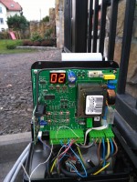
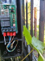
    At the beginning, I am not a specialist. Yesterday I completed the installation of the sliding gate with the faac 740 actuator. I connected the photo on the closing and bridged 5 out of 7 on the control panel. Unfortunately, the gate only opens. The pilot also programmed somehow strangely. The fsw cl diode is not on at all. I already read so much on the forum that my head hurts but I do not know how to solve this problem. I have a photo of xp20d and magnetic terminals. I also had an additional button in the garage connected to the open button and I disconnected the stop on the control panel for now, I thought that there was a problem here, but it's not that. Can anyone help.
  • ADVERTISEMENT
  • #2 16845501
    zybex
    Helpful for users
    You probably have a problem with the photocells. They detect an obstacle and therefore cannot close. Either you have NO turned on instead of NC, or the photos do not see each other (incorrectly aimed), or the sending photo has no power. As for the pilot, try without him for now. Short-circuit terminal 1 with 7 (open A), i.e. take out two cables and make a short circuit. Hope you bridged between 6 and 8 too.
    You can also always bypass the photocells by shorting 3 and 4 out of 11. Then the gate must close when you give the command.
  • #3 16846290
    Boku1
    Level 2  
    Hello
    1st bridge between 6 and 8 is
    2. What is it: Well, Nc
    3. I did as you said, I closed 1 of 7 and the gate opened like a remote control, but after another short circuit, no reaction, only the open A LED flashed, the gate did not move, the same effect as after clicking the remote control. I don't know what's going on, in the dark I already messed up something with cables that it didn't even open for me, but it can be recreated I think
    I have not taken 4 photos anymore. Too dark
  • #4 16846300
    zybex
    Helpful for users
    Boku1 wrote:

    2. What is it: Well, Nc

    NO - Normal Open (normally open)
    NC - Normal Close (normally closed)
    It concerns the state of the relay contacts. The relay contacts have three leads, COM, NO, and NC. It's such a switch. COM is in the middle and NO and NC are on the sides. So, depending on the needs, we use the contacts about which the instruction says.

    Faac 740 Sliding Gate Actuator Issue: Gate Only Opens, Wiring and FSW CL Diode Problems

    For you, FSW CL is off, which means that the protection has worked. You are to have a normally closed contact connected, as shown in the diagram. In addition, it's worth checking if the photos can be seen. After the optical barrier is broken, we need to hear the relay in the receiving photo.
  • ADVERTISEMENT
  • #5 16849371
    Boku1
    Level 2  
    You are to have a normally closed contact connected, as shown in the diagram. In addition, it's worth checking if the photos can be seen. After the optical barrier is broken, we need to hear the relay in the receiving photo.
    My wife passed the transmitter and something snapped. I checked the pics for the cables, cut them and then nothing. I got pissed off with the cables from the photos and I did according to fig. 5. And the gate works, although I won't say no, I have photos to hang on the posts, so that I will annoy this topic.
    Question from another fairy tale, I read on the forums that in order to have, for example, a switch to open in the garage, it is enough to have a simple bell and some write to connect open 1 with stop, others write open 1 with -. For me neither one nor the other works? I also set the E logic, but something with slowdowns is wrong.
    How, how can I check myself without taking photos, are they functional?
    Thanks for your help. Greetings
  • #6 16849439
    zybex
    Helpful for users
    Boku1 wrote:

    My wife passed the transmitter and something snapped. I checked the pics for the cables, cut them and then nothing.

    Between the transmitter and the receiver in standby mode there is a beam of invisible light (infrared). The receiver has a relay that turns on and off when the beam is interrupted. A characteristic "beep" can be heard in the receiver.
    In addition, the receiver has an additional diode, which optically signals the proper operation of this barrier. The relay has three contacts COM, NO and NC as standard. We always connect COM and the appropriate one as needed, in this case NC.
    You can see for yourself that omitting the photos and bridging everything according to Figure 5 gives the correct operation of the gate (there is also closing). So I don't see a big problem here, because when you properly connect these pics, it will work. If you are not sure about their work, use COM and NO, because there is no other option. Perhaps this is the "catch" here. You can understand the NC state in various ways, because I do not know when the relay is holding and when it is released? I don't have these pics (you have them) and you can easily check them as described above. You only have two choices, COM and NC or COM and NO.
    Boku1 wrote:

    Question from another fairy tale, I read on the forums that to have, for example, a switch in the garage to open, an ordinary bell is enough

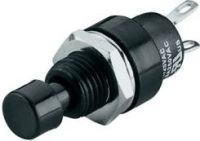
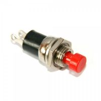
    As for the wired opening button (bell), you connect it under 1 and 7 (i.e. Open A and minus). You can put several such buttons in different places to make your life easier. Most often I installed miniature ones, because the currents flow there very little. Of course, the cable is also thin, eg telephone 2x0.5mm2. Someone requested in three places. Of course, if we want, we install an ordinary bell.
    Faac 740 Sliding Gate Actuator Issue: Gate Only Opens, Wiring and FSW CL Diode Problems Faac 740 Sliding Gate Actuator Issue: Gate Only Opens, Wiring and FSW CL Diode Problems
    I installed the visible ones in existing intercoms in a single-family house.
  • ADVERTISEMENT
  • #7 16849465
    kotbury
    Gantry automation specialist
    Quote:
    I do not have photos to hang on the posts, so that I will annoy this topic.

    What pics do you have? if Faacowskie, there are 2 LEDs on the receiver - one indicates power and the other - poorly visible and a little to the side - goes out after covering (and the relay in the receiving photo is clicked). If so, look for a problem in the cables or bad connection to the control panel.
    The previous speaker has already written about the button.
    Quote:
    I also set the E logic, but something with slowdowns is wrong.

    Specifically what?
    You can have a version with slows down before the limit switches (on time), i.e. rP in the menu - do not use this (set to zero) because it is unstable.
    The basic releases (the distance of which is set in the menu under the rA item) are the releases after the switch is activated (i.e. the limit switch will work and the gate continues to drive slowly through the distance in cm corresponding roughly to the rA value). This release is very short - max 7 cm - but sufficient - and you have to take it into account when setting the limit switches (i.e. set them a bit earlier).
  • #8 16849720
    Marek J.
    VIP Meritorious for electroda.pl
    zybex wrote:
    For you, FSW CL is off, which means that the protection has worked.

    Here I would only add that they can be damaged, badly connected, damaged cable etc ...
    It results from the photo, where you can see that fsw cl is off (and it should make the automatic start the closing cycle), and in the "light" of the photocells between the posts there is no obstacle.
  • #9 16849721
    kotbury
    Gantry automation specialist
    Quote:
    I do not have photos to hang on the posts, so that I will annoy this topic.

    What pics do you have? if Faacowskie, there are 2 LEDs on the receiver - one indicates power and the other - poorly visible and a little to the side - goes out after covering (and the relay in the receiving photo is clicked). If so, look for a problem in the cables or bad connection to the control panel. The FSW_CL diode should also go out (on uncovered photos).
    The previous speaker has already written about the button.
    Quote:
    I also set the E logic, but something with slowdowns is wrong.

    Specifically what?
    You can have a version of the drive with decelerations before the limit switches (on time), i.e. rP in the menu - do not use this (set to zero) because it is unstable.
    The basic releases in each 740/41 (the distance of which is set in the menu under the rA item) are the releases after a limit switch is activated (i.e. the limit switch will work and the gate will still drive slowly through the distance in cm corresponding roughly to the rA value). This release is very short - max 7 cm - but sufficient - and you have to take it into account when setting the limit switches (i.e. set them a bit earlier).
  • ADVERTISEMENT
  • #10 16851146
    Boku1
    Level 2  
    Thank you all for helpful advice. I have set the slowdown and before and after the krancowka. Tomorrow I will. The rest of the things are probably only from the next Friday I will have fun, unfortunately, but the end of free time and late with work I will return and in the dark it is not a job.
    I understand that it is about connecting with a cable either COM with NO or with NC.
    Damaged cables are not 100 percent of the time. Thanks again and let me know how to tinker with it
  • #11 16851941
    zybex
    Helpful for users
    Boku1 wrote:

    I understand that it is about connecting with a cable either COM with NO or with NC.

    You connect two cables. One to COM and the other to NO or NC. Besides, two cables for power supply (one can be common, according to the diagram).

    On a similar topic Kotbury He wrote about photocells such as yours, quotation: "As for the LED - TX should be on all the time (power), RX - one should be on all the time (power) and the other should be on as the photos can be seen and fade out when obscuring. the FSW CL LED on the control unit should behave. "

    Since you have this FSW CL off, you have a broken light beam or (more likely) a break to COM-NO (NC), i.e. replace one wire from NC to ON or vice versa. Simply in standby mode (photos can be seen) there should be a short circuit between COM and the second terminal (as in diagram 9).
    I do not know if the instruction from the photos tells exactly about this detail, i.e. when is NC and when NO. If you find it out, give me your answer here, because a similar assembly is coming soon.
  • #12 19650033
    fantomek
    Level 10  
    I will connect to the topic yesterday I changed the bulb in the siren. Faac 740 drive. Upon completion, the Gate operated both ways. The only thing is I didn't screw the antenna on because I forgot. Today the Gate only opens but does not close. What happened? What was reprogramming?
  • #13 19650130
    zybex
    Helpful for users
    Is it not possible to close the door with the button in the garage (direct control)?
    Probably something wrong with the photocells. The lack of an antenna has nothing to do with it.
    Check the photocells for contamination both from the outside and from the inside, if necessary. You can do the test by ignoring the photocells.
  • #14 19650197
    fantomek
    Level 10  
    Zybex, I do not have to close the entrance gate to the property in the garage, only via remote controls. I checked on two different remote controls and the same. I wrote about the lamp in this context that maybe some moisture got to it through the inlet where the antenna enters.
  • #15 19650286
    kotbury
    Gantry automation specialist
    As the previous speakers wrote - the lamp has nothing to do with it
    Are the FSW CL and FSW OP LEDs on? If you do not - you probably nudged the photo with your foot and the corroded wire released. Make working jumpers 3-4-11 in the control panel. If the gate regains closing - laborious searching for a break on the cables ...
  • #16 20049502
    gabi126
    Level 10  
    I have a similar problem, the gate worked with photocells, suddenly it can only be opened and not closed. Off FSW CL transmitting photocells on receiving photocells are on, two LEDs are on when there is a break, the beam one goes out and you hear the contactor, but nothing changes on the control unit.
    Where exactly are NC and NO in the photocell? or on the switchboard.
  • #17 20049655
    sisko
    Level 33  
    @ gabi126 in this topic Link you have a sample photo of a photocell.
    If the FSW CL is off, there is an open circuit somewhere or the relay in the photocell is not working properly.

    For the test, connect the terminal No. 4 to the terminal No. 7 or 8. The FSW CL LED should light up.

    The second test can be performed at the photocell, short-circuiting the wires going to the COM and NC or NO terminals, depending on how the given photocell performs this function.
    If the FSW CL LED is on, there is no interruption in the installation and the photocell is damaged.
  • #19 20050374
    gabi126
    Level 10  
    4 out of 7 lit up

    Added after 1 [hour] 2 [minutes]:

    The cable for 2 photos to 4 in the switchboard was bad. Works Thanks for your help

Topic summary

The discussion revolves around issues with a FAAC 740 sliding gate actuator, specifically that the gate only opens and does not close. The user has connected photocells incorrectly, leading to the FSW CL diode being off, indicating a problem with the photocell circuit. Various troubleshooting steps are suggested, including checking the wiring, ensuring the photocells are properly aligned, and verifying the relay connections (COM, NO, NC). Users recommend bypassing the photocells to test the gate's functionality and suggest that damaged cables or incorrect connections may be the root cause of the issue. The conversation also touches on the proper configuration of limit switches and the importance of ensuring that the photocells are operational.
Summary generated by the language model.
ADVERTISEMENT