logo elektroda
logo elektroda
X
logo elektroda

Can I connect DC to the AC heater? Will I damage the panel in the sun?

camfly1 42828 35
ADVERTISEMENT
Treść została przetłumaczona polish » english Zobacz oryginalną wersję tematu
  • #31 16627956
    gaz4
    Level 34  
    camfly1 wrote:

    Why is it worth controlling the power dissipated by the heater? (It wouldn't be difficult)


    As I wrote above, the real Umpp changes with the conditions under which PV works, especially with its temperature. If we want to reach the max, we should track the maximum power point on an ongoing basis, which requires the use of some algorithm with MPPT. With a constant heater resistance, it is de facto enough to follow the effective voltage on it - when it reaches the maximum, i.e. that the PV works at Umpp. Simple in theory but difficult in practice because simple measurement is not enough.

    http://ep.com.pl/artykuly/10079-Swiadomosc_pomiarow_Czy_swiadomie_mieomie_to_co_mieomie.html

    To determine the power on the heater, we need to measure True RMS. Since the regulator will change the frequency and width of the pulses, the voltage waveform on the heater may be very distorted and the normal voltage measurement will be for your dog's shed. Therefore, at the beginning, it is advisable to stick to a certain voltage band on PV, which will give a sufficiently high efficiency, and when everything is fine, you can try a real MPPT.
  • ADVERTISEMENT
  • #32 16642999
    camfly1
    Level 7  
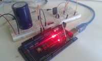
    OKAY. The transistors have arrived. I'm building on.

    The link on how to control them is above.

    Here is how to make a pwm controller from arduino:

    https://www.youtube.com/watch?v=r-qbZzIbt54

    Following the advice of gas4 to reduce battery efficiency (which would bring us closer to simulating PV as a source) I am adding two resistors in series at the input.

    Added after 30 [minutes]:


    Added after 52 [seconds]:

    Can I connect DC to the AC heater? Will I damage the panel in the sun?

    Added after 1 [minutes]:

    And my trivial app at the moment

    Can I connect DC to the AC heater? Will I damage the panel in the sun?

    Added after 10 [minutes]:

    As a load at the moment, instead of a heater, I gave a 12V / 2W bulb.
    It's starting to build a nice net, so it's high time for some scheme.

    The 100V / 45A transistor works great, but interestingly the gate pin must also be grounded. Otherwise, when it enters the excited state - and nothing discharges its potential - the transistor will let the current flow at will. I used a resistor to connect the gate to ground.

    I will make a diagram and post it.

    Of course, the programmer does not contain the PWM module yet, but it's only a matter of time :) .

    Added after 1 [hours] 17 [minutes]:

    A beautiful lecture on how to use an arduino thermometer:

    http://forbot.pl/blog/artykuly/programowanie/...o-ii-7-termometry-analogowe-i-cyfrowe-id18414

    I connect DS18B20.

    Added after 30 [minutes]:

    The thermometer works:
    Can I connect DC to the AC heater? Will I damage the panel in the sun?

    Added after 2 [minutes]:

    Hmm. It would be good to add a bluetooth module to control everything from the phone.
  • ADVERTISEMENT
  • #33 16643541
    gaz4
    Level 34  
    You probably didn't notice but this simple applet already regulates the power, no need to add any PWM module :) But first you need to change the electronics a bit. From what I deduce from the photo of "spider webs" you have a system: batteries - capacitor - resistors. It will not simulate PV, you need batteries - resistors - capacitor. There is still such a selection of resistors that after turning on the transistor, the voltage drops to
  • ADVERTISEMENT
  • #34 16643632
    camfly1
    Level 7  
    Eeejże dear colleague.
    I respectfully know what I am doing. After all, it was not by accident that I brought it to the current state. There were resistors between the power supply and the capacitor, but I only had half a watt and had to take them off. That's why they are not in the photo. In the next part I will try to connect a real panel.


    To build a truly effective PWM I am forced to deepen my knowledge of the maximum PV power point. I will be grateful for the links.

    I am also considering using the PWM arduino to power one water heater while using PV and wind farm. I understand that I will be forced to "boost" the voltage of both sources until I get the same voltage?
  • ADVERTISEMENT
  • #35 16643932
    gaz4
    Level 34  
    And you can ask what will be the difference between "true PWM" and the algorithm that switches the load on when the voltage rises above Umpp and disconnects it when it drops below Umpp? PWM is pulse width modulation and this simple algorithm in combination with a capacitor already implements it. If the current from PV is small, the capacitor will charge for a long time and discharge quickly - low charge. When the power is high, the PV will quickly charge the capacitor and when the load is switched on, it will effectively recharge it - high filling. But you can add a complicated algorithm to set the% modulation, set a fixed switching frequency, etc., goodies, the circuit will have exactly the same performance so you won't lose anything.

    Effective determination of Umpp requires checking the power obtained. I am an electronic dinosaur and when I was making electronic meters on the website, I was watching the "Poll" program broadcast on TV. Back then, complicated measurements were dealt with in various ways, and the TrueRMS measurement was important, for example, in determining the filament voltage of a kinescope. One of the methods was to measure the brightness of the bulb using a photoresistor. Here you can use a similar one, Umpp will be obtained when the bulb connected in parallel with the heater shines most strongly, and the measurement of the photoresistor resistance or the voltage on the photocell is a simple matter. The biggest disadvantage of this method will be the filament inertia, so the Umpp corrections should be made at large (several seconds) intervals.
  • #36 16653309
    camfly1
    Level 7  
    Thanks for the answers.

    I consider the topic exhausted because I found tie grid inverters that solve the problem of connecting to the network without the use of batteries.

    Despite this, the system works and is doing well.

    More important for me than obtaining a real mppt (it was already on the electrode) is the implementation of a hybrid regulator combining PV and a wind turbine based on arduino.

    So I will start a new topic because the name of the current one is misleading.

Topic summary

The discussion revolves around connecting 60V photovoltaic panels in series to power a 220V AC heater using a thermostat. Key concerns include the potential damage to unconnected panels in sunlight, the wear on these panels, and the feasibility of connecting a DC voltage to an AC heater. Responses indicate that while DC can be connected to the heater, it poses risks such as thermostat burnout due to arcing when disconnecting. Suggestions include using a heater driver, capacitors, and relays to mitigate arcing issues. The conversation also explores the use of PWM controllers and the importance of matching the heater's resistance to the photovoltaic output for optimal efficiency. Various solutions, including the use of triacs, SSRs, and specific relay models, are discussed to enhance system reliability and performance.
Summary generated by the language model.
ADVERTISEMENT