Hello everyone and thank you at the outset for your interest in this topic.
A few years ago, I described on this forum a balcony installation that still supplies my house with energy on sunny days.
https://www.elektroda.pl/rtvforum/topic3819236.html
Over time, I reduced the energy buffer from 105Ah to 65Ah, i.e. almost by half, due to the costs associated with cyclic replacement of this weakest link of the entire system.
Unfortunately, energy banks can only be afforded by people who have access to used cells, sponsor production companies on YouTube, and wealthy people - unfortunately, I do not belong to any of these groups - I am an ordinary electronics engineer with a passion.
Despite everything, my installation still works properly, protecting the devices on my farm against too high mains voltage on sunny days.
Over time, I began to optimize and measure the electrical and heating installations with the smart home system that I am building myself in my free time. To my surprise, it turned out that the biggest energy guzzler in my house was a 220-liter boiler, which was only set to heat at night.
The calculations show that the average daily energy demand for my four-person family is approximately 5.5 kWh in the period from April to November (outside the heating period).
This gives a result of approximately 1,150 kWh/year of energy demand just for maintaining domestic hot water.
I would like to mention that I regulate the temperature digitally, and the heater`s switch-off threshold is (or rather "was") 45°C with a hysteresis of 2°C.
I started counting…
-The period of reheating the buffer from the network is approximately 7 months (let`s assume 210 days).
-The boiler has an average demand of 5.5 kW/day
-Thermal losses through the tank jacket are up to 50W/h.
-This gives a daily loss of stored energy of >1kWh
-Higher losses can be achieved by using hot water circulation.
-In mid-March, the length of the day is 12H and the height of the sun above the horizon already exceeds 35°
-Theoretically, we should extract 5.5kWh from a 1.5kW PV installation on a sunny day.
I had to build a garden shed 20 meters behind the house and it was a miracle that I didn`t start making the roof from metal tiles.
The location of the garden shed was ideally south, however, I wanted to tilt the roof south for aesthetic reasons with an angle no greater than 8°, and to my surprise, using a calculator for photovoltaic installations, it turned out that in the summer, such an arrangement of the photovoltaic installation can start production at more than an hour earlier, which also applies to the end of production.
The roof surface allowed for the installation of six panels with a total power of 1440Wp.
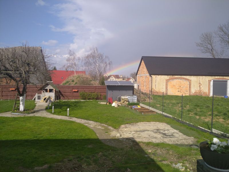
Initially, I connected the installation using Ohm`s law directly to the heater, using the IGBT transistor as a switch. Everything worked fine, but I think I forgot something?!
Sure, MPPT…
After just a few days, it was noticeable that the installation was working poorly in the mornings and evenings, which resulted in me losing several dozen percent of efficiency. So I started searching the web for solutions.
I found a few ready-made drivers, but the price scared me a bit. After all, I had already spent PLN 1,700 for the panels with cables and connectors, and I wanted a return on the investment within, preferably, no more than 2 years.
So I kept looking and…
I came across a few designs, so I started playing.
-The first controller was simple, based on a transistor, a choke and a bit of wirework, which I prefer not to describe - the losses were still over 10%
-The next one was based on WEMOS D1 mini and ADS1115 - Unfortunately, it often crashed.
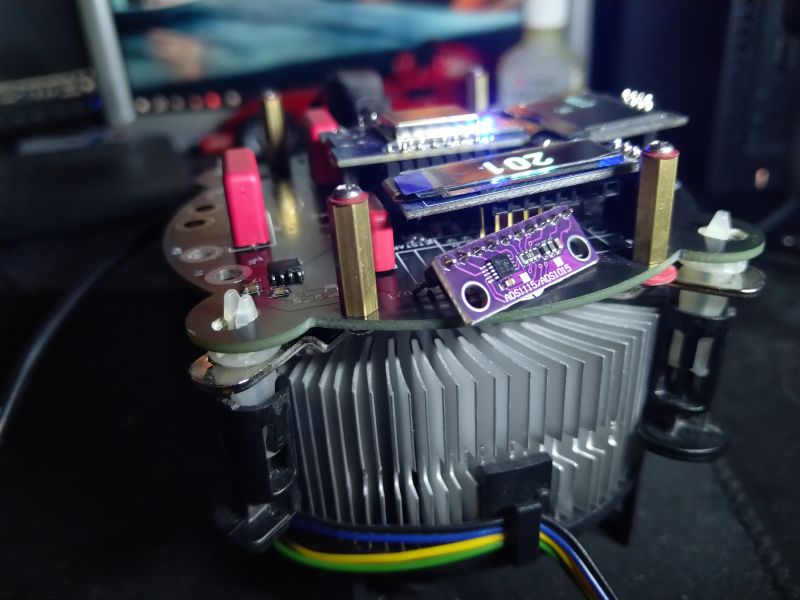
-I based the next controller on the popular Arduino NANO and several readily available components. Unfortunately, even though I didn`t spend more than PLN 50 on it, since I had practically everything on hand, I wasn`t satisfied with it, because as it turned out, I didn`t have the right Mosfet transistors in stock. The resistance during conduction turned out to be very important, which one day led to the transistor being damaged and the water in the buffer almost boiling.
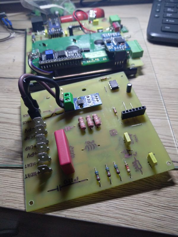
-And another...
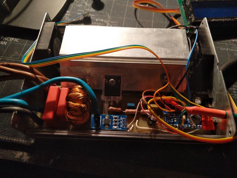
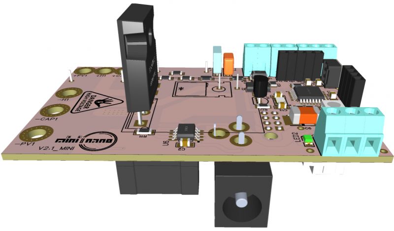
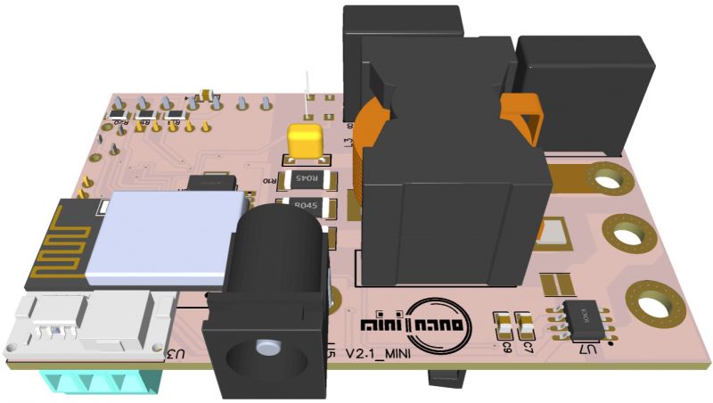
-I tried to make the next drivers based on appropriately selected components and I started to figure out the pros and cons, taking into account available Open Source solutions as well as the capabilities of drivers available on the market, and here is the version of the MPPT driver, which I called
mini2nano_V2.1
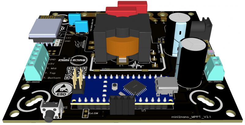
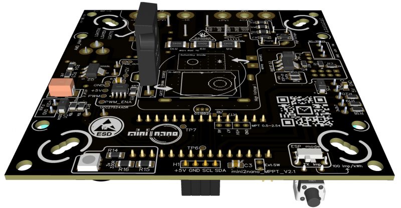
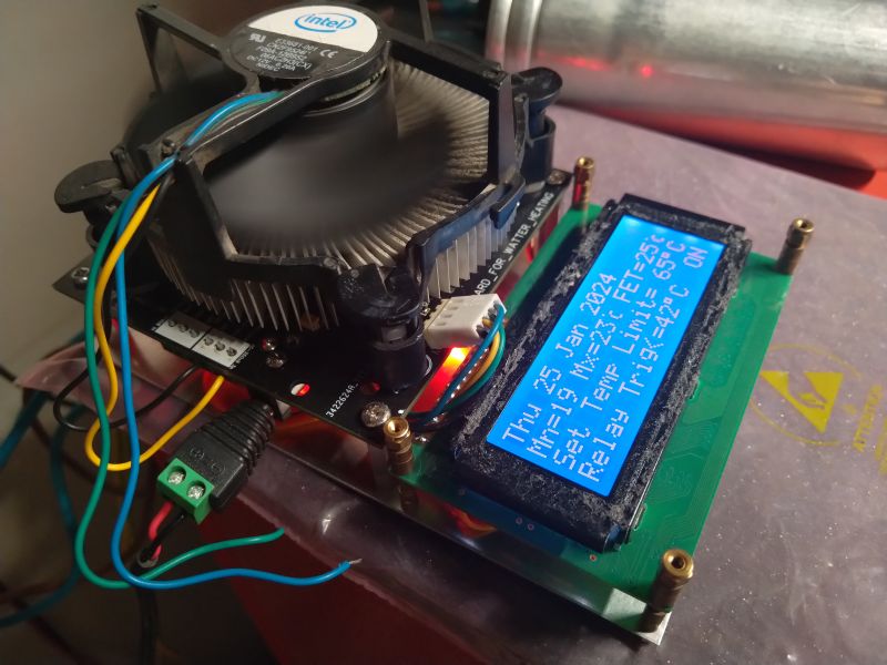
And here are its possibilities:
-Voltage range from the PV installation <250VDC OpenCircuit (it is possible to increase the range - the IPC-2221 standard was used for PCBs).
-Maximum current <16A (It is possible to increase the range with the ACS712-30A module and by increasing the track thickness from 1oz to 2oz)
-The maximum power is therefore approximately 3.75kW
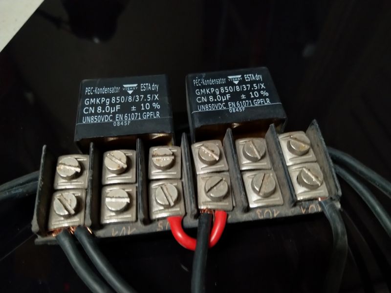
-A 200uF capacitor is used for smooth operation (buffer operation)

-Path topology allows for individual selection of components such as: Mosfets, Schottky diodes, drivers, capacitors, etc.)
-The MPPT P&O algorithm was used, with an efficiency exceeding 99%, with the possibility of replacing it with another one.
-Control of tank temperatures in three levels (Bottom, middle, top) - Why three sensors, you ask? The next point will explain.
- An additional output for an external relay has been implemented in case the weather is not good (the controller will connect e.g. a network heater located halfway up the tank and heat the upper part of the "Available water" buffer to a set value, e.g. 43ᵒC)
-Added the possibility of using proven cooling systems for passive elements (a 12V fan connector has been added, activated after exceeding the set temperature - initially 35ᵒC)
-The PCB has been designed so that it is possible to use computer fans with Intel LGA775, LGA155X, LGA1700 and AMD AM4 series sockets (prepared mounting holes)
-It is possible to mount the board to any heat sink using the pressure method (all passive SMD components mounted on one side of the PCB)
-It is possible to change the frequency of the PWM signal in the range of 2kHz – 17kHz.
-For temperature protection of the Mosfet transistor, an additional DS18B20 temperature sensor is used in the heat sink area)
-An additional connector has been added for individual project expansion (2x analog-digital input/output)
-An additional connector has been added for the ESP-01 Wi-Fi module or ESP-01s based on the well-known ESP8266 for data transfer to client applications such as Supla, Tasmota, Domoticz…
-It is possible to choose whether we want data transmission from Arduino Nano or a 100imp/kWh pulse signal at the ESP8266 Rx input.
-Added DS18B20 buffer temperature sensor connector on PCB for ESP-01s.
-For efficient operation, a Mosfet driver with a current capacity of 5A is used
-An RGB LED has been added to inform about the device status.
-The board is made using the lead-free method, i.e. "RoHS compilant" - if it`s ECO, it`s a bad idea.
-The program performs a full system test before starting work and during work:
-Checks the voltage range of the 12VDC power supply (The power supply allows you to extract every Watt from the panels.
-Checks buffer and mosfet temperatures.
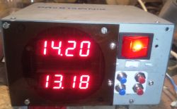
-The device uses an LCD2004 display via the I2C bus (long-lasting and proven)
-The display will show, among others:
-Current PV voltage
-Current PV intensity
-The current power of the system.
-PWM signal drive level
-Current buffer temperatures
-Maximum daily buffer temperatures
-Current cooling system temperature
-Error messages in Polish
-Information on the status of the signal output for the additional heater
-Date
-Total daily production.
- Pinout of the display connector allows for easy installation of a display such as OLED SSD1306, however, due to the extensive Adafruit library, it is not possible to write code for multiple displays at the same time (I decided to leave the topic of OLED for dessert)
-A connector for an external button has been added if we want to mount the PCB in the box.
-Through the USB connector and UART connected to the ESP-01s connector, it is possible to set the following values:
-Date stored in EPROM memory (RTC clock removed - date will change automatically after dark)
-Temperature ranges:
-Buffer (pre-set to 65ᵒC)
-Additional external heater (pre-set to 43ᵒC)
-System cooling temperatures (pre-set at 35ᵒC)
-Additionally, via USB, UART we can:
-Call the command to start or turn off the system.
-Invoke the full test command for PWM signals showing the peak value and MPP power point
-Determining any PWM signal drive value.
-Monitor the values of analog inputs and their values converted into Amps, Volts for the purpose of calibrating the system.
-Call the intuitive MENU with a description in Polish, of course
-Erase the EPROM memory
-Send current values on request
-Inquire about historical values.
Someone will say, hey, another controller also has a graph on the display, but this one doesn`t.
That`s right. But the display used in my case costs about PLN 20, and if you insist, it is unnecessary, because thanks to the Wi-Fi module we have access to charts and history for free, as far back as we want, without additional SUBSCRIPTIONS, and best of all, we can choose which platform we send data to.
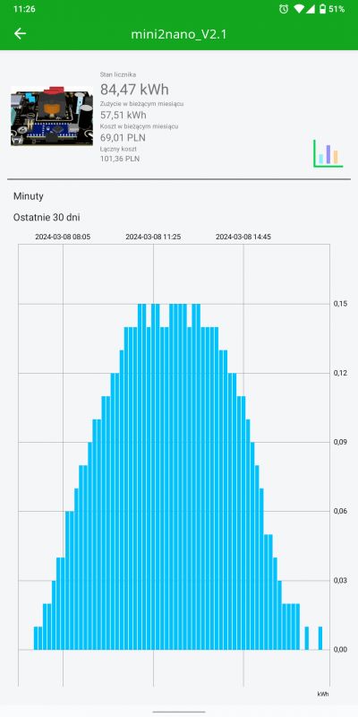
Data saved every 10 minutes.
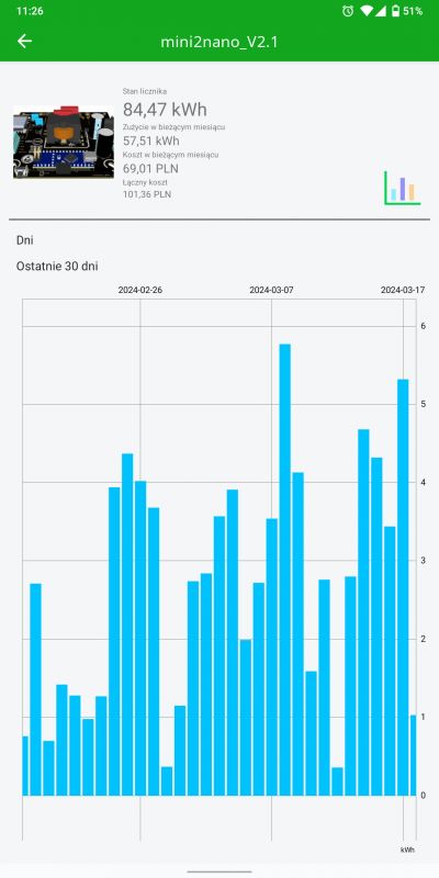
This is the monthly production in the gloomy period of February - March
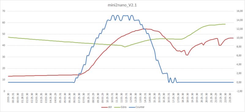
Example of exporting power and temperature data to Excel from the sunny day of March 8, 2024.
You say, and another controller does not need a fan.
You don`t need this one either - all you need is a suitable radiator (sometimes we have one on hand for free)
Someone will ask - What about casing and security?
The PCB has dimensions of 98mm x 98mm - There will definitely be a dedicated box - after all, it is a DIY project.
What about DC safety?
We are on the Elektroda forum after all...
I designed the controller using the IPC-2221 standard.
All closed-mode switching power supplies have >300V DC inside the housing.
In addition, 90% of PV water heating controllers operate on direct current.
I have been developing the project for about a year and have recently been posting the progress on my YouTube channel
@mini2nano
Last year, between April and October, the PV installation successfully transferred 970kWh to the buffer, and I took less than 2kWh from the grid during the energy shortage in autumn.
In short, the installation paid for itself in half within a year.
If you liked the project, I will be very grateful for your support by subscribing to my channel and possibly Like...
A few years ago, I described on this forum a balcony installation that still supplies my house with energy on sunny days.
https://www.elektroda.pl/rtvforum/topic3819236.html
Over time, I reduced the energy buffer from 105Ah to 65Ah, i.e. almost by half, due to the costs associated with cyclic replacement of this weakest link of the entire system.
Unfortunately, energy banks can only be afforded by people who have access to used cells, sponsor production companies on YouTube, and wealthy people - unfortunately, I do not belong to any of these groups - I am an ordinary electronics engineer with a passion.
Despite everything, my installation still works properly, protecting the devices on my farm against too high mains voltage on sunny days.
Over time, I began to optimize and measure the electrical and heating installations with the smart home system that I am building myself in my free time. To my surprise, it turned out that the biggest energy guzzler in my house was a 220-liter boiler, which was only set to heat at night.
The calculations show that the average daily energy demand for my four-person family is approximately 5.5 kWh in the period from April to November (outside the heating period).
This gives a result of approximately 1,150 kWh/year of energy demand just for maintaining domestic hot water.
I would like to mention that I regulate the temperature digitally, and the heater`s switch-off threshold is (or rather "was") 45°C with a hysteresis of 2°C.
I started counting…
-The period of reheating the buffer from the network is approximately 7 months (let`s assume 210 days).
-The boiler has an average demand of 5.5 kW/day
-Thermal losses through the tank jacket are up to 50W/h.
-This gives a daily loss of stored energy of >1kWh
-Higher losses can be achieved by using hot water circulation.
-In mid-March, the length of the day is 12H and the height of the sun above the horizon already exceeds 35°
-Theoretically, we should extract 5.5kWh from a 1.5kW PV installation on a sunny day.
I had to build a garden shed 20 meters behind the house and it was a miracle that I didn`t start making the roof from metal tiles.
The location of the garden shed was ideally south, however, I wanted to tilt the roof south for aesthetic reasons with an angle no greater than 8°, and to my surprise, using a calculator for photovoltaic installations, it turned out that in the summer, such an arrangement of the photovoltaic installation can start production at more than an hour earlier, which also applies to the end of production.
The roof surface allowed for the installation of six panels with a total power of 1440Wp.

Initially, I connected the installation using Ohm`s law directly to the heater, using the IGBT transistor as a switch. Everything worked fine, but I think I forgot something?!
Sure, MPPT…
After just a few days, it was noticeable that the installation was working poorly in the mornings and evenings, which resulted in me losing several dozen percent of efficiency. So I started searching the web for solutions.
I found a few ready-made drivers, but the price scared me a bit. After all, I had already spent PLN 1,700 for the panels with cables and connectors, and I wanted a return on the investment within, preferably, no more than 2 years.
So I kept looking and…
I came across a few designs, so I started playing.
-The first controller was simple, based on a transistor, a choke and a bit of wirework, which I prefer not to describe - the losses were still over 10%
-The next one was based on WEMOS D1 mini and ADS1115 - Unfortunately, it often crashed.

-I based the next controller on the popular Arduino NANO and several readily available components. Unfortunately, even though I didn`t spend more than PLN 50 on it, since I had practically everything on hand, I wasn`t satisfied with it, because as it turned out, I didn`t have the right Mosfet transistors in stock. The resistance during conduction turned out to be very important, which one day led to the transistor being damaged and the water in the buffer almost boiling.

-And another...

-I tried to make the next drivers based on appropriately selected components and I started to figure out the pros and cons, taking into account available Open Source solutions as well as the capabilities of drivers available on the market, and here is the version of the MPPT driver, which I called
mini2nano_V2.1


And here are its possibilities:
-Voltage range from the PV installation <250VDC OpenCircuit (it is possible to increase the range - the IPC-2221 standard was used for PCBs).
-Maximum current <16A (It is possible to increase the range with the ACS712-30A module and by increasing the track thickness from 1oz to 2oz)
-The maximum power is therefore approximately 3.75kW
-A 200uF capacitor is used for smooth operation (buffer operation)

-Path topology allows for individual selection of components such as: Mosfets, Schottky diodes, drivers, capacitors, etc.)
-The MPPT P&O algorithm was used, with an efficiency exceeding 99%, with the possibility of replacing it with another one.
-Control of tank temperatures in three levels (Bottom, middle, top) - Why three sensors, you ask? The next point will explain.
- An additional output for an external relay has been implemented in case the weather is not good (the controller will connect e.g. a network heater located halfway up the tank and heat the upper part of the "Available water" buffer to a set value, e.g. 43ᵒC)
-Added the possibility of using proven cooling systems for passive elements (a 12V fan connector has been added, activated after exceeding the set temperature - initially 35ᵒC)
-The PCB has been designed so that it is possible to use computer fans with Intel LGA775, LGA155X, LGA1700 and AMD AM4 series sockets (prepared mounting holes)
-It is possible to mount the board to any heat sink using the pressure method (all passive SMD components mounted on one side of the PCB)
-It is possible to change the frequency of the PWM signal in the range of 2kHz – 17kHz.
-For temperature protection of the Mosfet transistor, an additional DS18B20 temperature sensor is used in the heat sink area)
-An additional connector has been added for individual project expansion (2x analog-digital input/output)
-An additional connector has been added for the ESP-01 Wi-Fi module or ESP-01s based on the well-known ESP8266 for data transfer to client applications such as Supla, Tasmota, Domoticz…
-It is possible to choose whether we want data transmission from Arduino Nano or a 100imp/kWh pulse signal at the ESP8266 Rx input.
-Added DS18B20 buffer temperature sensor connector on PCB for ESP-01s.
-For efficient operation, a Mosfet driver with a current capacity of 5A is used
-An RGB LED has been added to inform about the device status.
-The board is made using the lead-free method, i.e. "RoHS compilant" - if it`s ECO, it`s a bad idea.
-The program performs a full system test before starting work and during work:
-Checks the voltage range of the 12VDC power supply (The power supply allows you to extract every Watt from the panels.
-Checks buffer and mosfet temperatures.
-The device uses an LCD2004 display via the I2C bus (long-lasting and proven)
-The display will show, among others:
-Current PV voltage
-Current PV intensity
-The current power of the system.
-PWM signal drive level
-Current buffer temperatures
-Maximum daily buffer temperatures
-Current cooling system temperature
-Error messages in Polish
-Information on the status of the signal output for the additional heater
-Date
-Total daily production.
- Pinout of the display connector allows for easy installation of a display such as OLED SSD1306, however, due to the extensive Adafruit library, it is not possible to write code for multiple displays at the same time (I decided to leave the topic of OLED for dessert)
-A connector for an external button has been added if we want to mount the PCB in the box.
-Through the USB connector and UART connected to the ESP-01s connector, it is possible to set the following values:
-Date stored in EPROM memory (RTC clock removed - date will change automatically after dark)
-Temperature ranges:
-Buffer (pre-set to 65ᵒC)
-Additional external heater (pre-set to 43ᵒC)
-System cooling temperatures (pre-set at 35ᵒC)
-Additionally, via USB, UART we can:
-Call the command to start or turn off the system.
-Invoke the full test command for PWM signals showing the peak value and MPP power point
-Determining any PWM signal drive value.
-Monitor the values of analog inputs and their values converted into Amps, Volts for the purpose of calibrating the system.
-Call the intuitive MENU with a description in Polish, of course
-Erase the EPROM memory
-Send current values on request
-Inquire about historical values.
Someone will say, hey, another controller also has a graph on the display, but this one doesn`t.
That`s right. But the display used in my case costs about PLN 20, and if you insist, it is unnecessary, because thanks to the Wi-Fi module we have access to charts and history for free, as far back as we want, without additional SUBSCRIPTIONS, and best of all, we can choose which platform we send data to.

Data saved every 10 minutes.

This is the monthly production in the gloomy period of February - March

Example of exporting power and temperature data to Excel from the sunny day of March 8, 2024.
You say, and another controller does not need a fan.
You don`t need this one either - all you need is a suitable radiator (sometimes we have one on hand for free)
Someone will ask - What about casing and security?
The PCB has dimensions of 98mm x 98mm - There will definitely be a dedicated box - after all, it is a DIY project.
What about DC safety?
We are on the Elektroda forum after all...
I designed the controller using the IPC-2221 standard.
All closed-mode switching power supplies have >300V DC inside the housing.
In addition, 90% of PV water heating controllers operate on direct current.
I have been developing the project for about a year and have recently been posting the progress on my YouTube channel
@mini2nano
Last year, between April and October, the PV installation successfully transferred 970kWh to the buffer, and I took less than 2kWh from the grid during the energy shortage in autumn.
In short, the installation paid for itself in half within a year.
If you liked the project, I will be very grateful for your support by subscribing to my channel and possibly Like...
Cool? Ranking DIY


