Hello all.
For some time now I have been considering buying "high voltage" panels. For starters, I think about 2-3 panels for a trial. My choice fell on used amorphous panels due to their availability and a specific price in Poland.
The panels are initially to be used to support the heating of utility water, but later I am thinking of extending their use to illuminate the plot (battery + leds)
And here comes the first question:
 Can such used panels be useful for something or is it not worth having fun (because when the German mentions them, he has already used them up enough)
 What to look for when buying used panels, what basic tests should be carried out when choosing panels from a palette, e.g. 50 pieces
 How to connect the panels
  I am thinking of increasing the voltage by series connection.
Next, I'd like to build a regulator that tracks the maximum duty point.
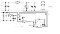
I would make DC / DC converters lowering the voltage, the heart of which would be an arduino (unless I find a ready control system).
Such a system would measure the current and voltage and, on the basis of the obtained data, calculate the power and increase or decrease the voltage (and thus increase the current on the load).
Here I have the following questions:
 Is the step-down converter circuit suitable for my circuit
  Is it better to use a voltage increase and decrease system?
 How to perform a current measurement
  Whether the DC / DC converter input will be pulsed, making the measurement difficult. Would the current be only slightly undulated at the DC / DC output? I would use the ACS709 or similar current sensor for the measurement.
 Where to measure the voltage at the input from the panels or at the output of the converter
  The measurement would be made on a simple resistive bridge.
 What heaters should I use if I had 2 panels? Whether to use one heater permanently on or, for example, 3 and control their switching on due to the supplied power
Thanks in advance for your responses and constructive criticism.
When I start working on this project, I will be adding more posts.
For some time now I have been considering buying "high voltage" panels. For starters, I think about 2-3 panels for a trial. My choice fell on used amorphous panels due to their availability and a specific price in Poland.
The panels are initially to be used to support the heating of utility water, but later I am thinking of extending their use to illuminate the plot (battery + leds)
And here comes the first question:
Next, I'd like to build a regulator that tracks the maximum duty point.
I would make DC / DC converters lowering the voltage, the heart of which would be an arduino (unless I find a ready control system).
Such a system would measure the current and voltage and, on the basis of the obtained data, calculate the power and increase or decrease the voltage (and thus increase the current on the load).
Here I have the following questions:
Thanks in advance for your responses and constructive criticism.
When I start working on this project, I will be adding more posts.


