logo elektroda
logo elektroda
X
logo elektroda

Can I connect DC to the AC heater? Will I damage the panel in the sun?

camfly1 42828 35
ADVERTISEMENT
Treść została przetłumaczona polish » english Zobacz oryginalną wersję tematu
  • #1 16613227
    camfly1
    Level 7  
    Hello.

    I have a few questions about renewable energy sources.
    Namely, I would like to connect several 60V 1.2A 1000Vmax photovoltaic panels in series to get a voltage of about 220V and connect with a thermostat to the 220V AC heater. The thermostat would disconnect the panels after obtaining the right water temperature in the tank.
    This way, I bypass the need to buy batteries, a charge regulator, etc. I store all my energy as heat in an insulated tank.

    And here are my questions - maybe a bit strange - to which I cannot find answers:
    1. Will unconnected panels in the sun be damaged?
    2. Are unconnected panels in the sun subject to "normal" wear?
    3. Can the AC 220V heater - which is, after all, an ordinary resistor - be connected to DC voltage?

    Greetings.
  • ADVERTISEMENT
  • #2 16613238
    Rezystor240
    Level 42  
    camfly1 wrote:
    3. Can the AC 220V heater - which is, after all, an ordinary resistor - be connected to DC voltage?


    Yes, of course, you can connect direct current to the heater.

    I will not say more because I do not want to mislead you.
  • Helpful post
    #3 16613243
    prose
    Level 35  
    camfly1 wrote:
    1. Will unconnected panels in the sun be damaged?

    Not
    camfly1 wrote:
    2. Are unconnected panels in the sun subject to "normal" wear?

    Yes.
    camfly1 wrote:
    3. Can the AC 220V heater - which is, after all, an ordinary resistor - be connected to DC voltage?

    Yes, but the thermostat will be damaged when DC is connected to the heater, the arc.

    Added after 2 [minutes]:

    It is best to use a heater driver.
  • ADVERTISEMENT
  • Helpful post
    #4 16613336
    Jan_Werbinski
    Level 33  
    You may burn the thermostat on the very first day. Be sure to use a heater driver. I saw one for PLN 500.
  • #5 16613809
    camfly1
    Level 7  
    Oh my. Thank you for such quick answers.
    Could you please explain the thermostat burnout phenomenon? Let's assume the thermostat is W1209 and the panels do not exceed 230V / 10A. Why would it burn out?
    The driver for PLN 500 makes my heart sting a little ... and my eyes are spinning.
  • #6 16614148
    prose
    Level 35  
    When DC voltage is disconnected, an arc is generated and the contacts burn out.
  • ADVERTISEMENT
  • #8 16614338
    prose
    Level 35  
    Good example, fire hazard.
  • Helpful post
    #9 16614364
    Matheu
    Level 25  
    camfly1 wrote:
    Namely, I would like to connect several 60V 1.2A 1000Vmax photovoltaic panels in series to get a voltage of about 220V and connect with a thermostat to the 220V AC heater.
    Buddy - maybe you can give the POWER of this heater?

    Thermostat W1209 Sample link :
    Output load: up to 2300 W
    20A / 12V DC
    10A / 230V AC
    With direct current - the possible breaking current of such a (ordinary) relay will drop significantly

    You want to connect panels (60V / 1.2A) in series - that is, the efficiency of the source will probably not be greater than these 1.2A, but:
    here is a very nice demonstration - the difference between AC and DC only
    Disconnecting DC current
  • #10 16615329
    gaz4
    Level 34  
    You can connect DC to the heater but it carries a lot of limitations. It has already been written about the thermostat, most of it will burn during the first disconnection. This can be avoided and in my topic about the boiler and two heaters there is a discussion about it. The simplest solution is a capacitor + bulb whose task is to make a divider when the thermostat is disconnected, which reduces the voltage that occurs on it = spark reduction even to zero (mainly depends on the power of the bulb, the bigger the better). Another thing is to connect the PV to get around 220V as I understand in the power point. The problem is that the maximum voltage after disconnecting the heater may exceed 300V, which increases the risk of damaging various components. Another thing is to match the constant resistance of the heater to the PV power that changes with the insolation - this way, you can get a maximum of 70% efficiency, but on the condition of the correct selection of the heater's power to the power and voltage of PV. If we choose them incorrectly, even on a sunny day, PV will heat with half or even 1/4 of its power.
  • #11 16615391
    camfly1
    Level 7  
    Matheu great presentation. Thanks.
    I know a little about arduino programming. What if I made a simple PWM controller out of the relay and the relay? Will the "square" current 0v-220v-0v-220v 50Hz work in this case? (There will be no bow?)
    Gas4
    The PWM controller should also control the power of the panels and the arduino can be made a thermostat with a dedicated thermometer. Am I looking well?
  • #12 16615453
    gaz4
    Level 34  
    The arc on the thermostat is the easiest problem to solve. If you can make a PWM controller looking for a maximum power point and a thermostat function, you have a solution to almost all problems related to connecting the heater and PV. By the way, somewhere here is a topic in which the construction of PWM is discussed, only that from discrete elements.
  • #13 16615513
    camfly1
    Level 7  
    Still, gentlemen, I expect confirmation that the impulse current will protect the thermostat against an arc when disconnected.
    I have already ordered three pieces for PLN 8 for testing. ;)

    Gas4
    I see you have knowledge of the power point. Let's assume that I can read the voltage provided by the panels with the help of the arduino. We know the constant resistance of the heater. I can use a programmed ard and a relay to send pulses to the heater. Maybe if you explained to me how to achieve maximum heater power with changing voltage, we would somehow bite it. At the end of the ardu with additions it costs about PLN 35 and I find these heater regulators from PLN 1000 up.

    Added after 44 [minutes]:

    Heh. Matheu's question about the power of the heater is spot on.
    For example, suppose I want to use a 220V 1kW heater. Simple calculations show that the heater will be able to release 4.5A and has a resistance of 48ohm. (besides they are inexpensive about PLN 50). I understand that if I were to let go of these 1.2 A, I would get a maximum voltage of 57V and a total of 62W. Which is nothing.
    So it would be better to use a 600W 48V heater (these are expensive PLN 250) and connect the panels in parallel to obtain a higher amperage. True?
  • #14 16615767
    Matheu
    Level 25  
    Gas4
    Capacitor and high-power bulb - a very interesting idea. Can you say more? As I understand it - a branch with a capacitor and a bulb - connected in parallel to the relay contacts, right?
    What would be the approximate capacity value (and bulb power) for a 220V DC / 1kW heater?

    Camfly1
    a) the presentation "AC / DC disconnection" is not by me, I just threw the link

    b) yes, the pulse current (0V .. max V .. 0V .. max V .. 0V) would limit the arc formation (or rather it would extinguish the arc) on the relay, just say - how do you want to get such a pulse current - using another relay ?

    c) The topic interested me a bit. There is such a producer of relays, e.g. Relpol, it has a wide selection, I looked for:
    https://www.relpol.pl/Produkty/
    (lower part of the page) -> Relays for photovoltaic panels

    In my opinion, the Relpol series RUC-M ( DC heavy duty relays with magnetic blowout ) would meet your requirements:
    load in category DC1 (resistive load, e.g. heater)
    12A / 220V DC (for the 1Z version of the relay, in this case there is a double width of the insulation gap or, I suppose, it may be "special construction" - the current normally flows through a set of two contacts one-by-one, and when disconnecting the arc is divided by two parts, by two interruptions , each of the usual width)
    There are versions for coils AC or DC, when looking at your W1209 thermostat, you are interested in the 12V DC coil.

    The second thing:
    There is also the issue of the current consumption by the coils of this RUC-M relay. The relay is bigger so I expect that may be bigger?
    by datasheet:
    rated power consumption (DC coil version) 1W - for estimation
    coil resistance (for 12V DC version) 85 Ohm => I = U / R ~ 140mA

    You can measure the resistance of the relay coil built into the thermostat, if it is less - SUPER!
    II way - check: disconnect the relay from the board and load the points where the relay coil was, but - with excessive load, you can burn the board ...
    or / ask the manufacturer how much the board will be able to supply the current to the coil
    Please write - what have you achieved!

    greetings - Maciek
    Attachments:
  • #15 16615795
    camfly1
    Level 7  
    Matheu
    ad.b) I was going to achieve a pulse current with a dedicated arduino relay. (I do not want to give a link that will expire with time - just enter "arduino 230v relay" in google) But of course the arc will be formed on the relay.

    1.I am thinking of two solutions to the arc problem:
    a) Should the arcing phenomenon not disappear at lower panel voltage (parallel connection up to 60V)?
    b) gas4
    They are dedicated to arduino shielda with four relays. Following your advice gas4: connect the panels in parallel to the two relays. I program the ard so that after reaching the temperature, just before disconnecting the heater, it connects a second load on another relay (with low resistance), thus lowering the voltage. Will it be ok?

    2. The problem of obtaining the maximum possible power with changing voltages of the panels:
    Reading the voltages of the panels with an arduino is doable. I understand that the way to control the power will be to give the right intensity to the heater?
  • Helpful post
    #16 16615850
    Jan_Werbinski
    Level 33  
    As for the arc problem itself, I suggest using a triac or SSR, or an eternal relay. It could even be controlled by a bimetallic thermostat.
    http://elportal.pl/pdf/k07/19_12g.pdf
    The question of controlling the operating point of the panels remains.
  • #17 16615870
    kot mirmur
    Level 33  
    Triac in DC circuit? How will colleague Jan steer it?
  • #18 16615949
    elektryku5
    Level 39  
    Matheu wrote:
    The second thing:
    There is also the issue of the current consumption by the coils of this RUC-M relay. The relay is bigger so I expect it could be bigger?
    by datasheet:
    rated power consumption (DC coil version) 1W - for estimation
    coil resistance (for 12V DC version) 85 Ohm => I = U / R ~ 140mA


    I would prefer a contactor, you can get even cheaper than this relay, and the contacts are rather more reliable, you can control the contactor from the relay that is already in the thermostat, the only disadvantage is that the contactor's coil takes a little more power, then it in turn one could still think about some mosfet or IGBT and check whether the overall losses at the transistor junction or the relay / contactor coil will be lower.
  • ADVERTISEMENT
  • #19 16616262
    Wojte1199
    Level 19  
    Take a look at a regulator such as BRIZO, it will arrange everything for you together with the measuring thermostat, etc. Regards and good luck with PV
  • #20 16616564
    camfly1
    Level 7  
    Wojte1199
    Does this wind regulator not need a battery? If so, what does gingerbread have for a windmill? Have you read the thread from the beginning? Do you connect to the topic just to push your product?

    However, it is with great pleasure that I read the answer of Mr. Jan Werbiński. The amount of confidence in solving the first problem is fascinating. In my search, I also came across a solution using a triac and arduino (they are to control the solar panels together with the pump). Mr. John, how would you connect it? Could you be tempted to explain and even a small sketch of the scheme?
  • #21 16616592
    Wojte1199
    Level 19  
    [quote = "camfly1"] Wojte1199
    Does this wind regulator not need a battery? If so, what does gingerbread have for a windmill? Have you read the thread from the beginning? Do you connect to the topic just to push your product?

    It's not my product! You don't need a battery. I have 8 similar panels in a row. Heater 2000W 230v. Everything is controlled by the brizo driver just mentioned. Anyway, there are several installations on the electrode built on BRIZO.
  • #22 16616630
    Leon444
    Level 26  
    Brizo is a revelation and the contractor will select an executive module for the operating voltage you want to maintain, I have 4 Brizo HV drivers and they are great, I have 3 Brizos on Mosfets up to 200V and one on IGBT up to 400V
    I am also not the manufacturer of this driver, nor do I have any of it, just my opinion as a user for 2 years ...
  • #23 16617133
    Jan_Werbinski
    Level 33  
    camfly1 wrote:

    However, it is with great pleasure that I read the answer of Mr. Jan Werbiński. The degree of confidence in solving the first problem is fascinating. In my search, I also came across a solution using a triac and arduino (they are to control the solar panels together with the pump). Mr. John how would you need this

    At home, I use triacs and SSR relays for heating, but for alternating current. As for the solid, I do not heat water with it, I only charge the batteries.
    The idea is to control the semiconductor element, which excludes the formation of an arc.
  • Helpful post
    #24 16617539
    gaz4
    Level 34  
    The implemented protection by means of a capacitor and a bulb is here:

    https://www.elektroda.pl/rtvforum/topic3223621-90.html#16578733

    The selection of elements depends on the quality of the thermostat (I came across one that does not spark without modifications!) And the inductance of the heater. In most cases, a 220-470nF capacitor removed from the old PC power supply was sufficient, the most resistant contact was sufficiently protected by a 60W bulb, but the higher the better (lower cold filament resistance = lower voltage during switching).

    camfly1 wrote:

    They are dedicated to arduino shielda with four relays. Following your advice gas4: connect the panels in parallel to the two relays. I program the ard so that after reaching the temperature, just before disconnecting the heater, it connects a second load on another relay (with low resistance), thus lowering the voltage. Will it be ok?


    Such circuits are best done on electronic components. Connecting an additional load would be ineffective, when deciding to control the relay, it is better to make a system with two heaters as in the diagrams in my topic. The heater shorted by the relay would act as a protection against sparking. In my driver I use cheap Chinese relays as in one of the photos and apart from the 220nF capacitor, there are no other protections, nothing sparking. So, as a relay, there are either two heaters in series, one of which is used as a protection, or instead of using a light bulb or some heater. The limitation of the above-mentioned solution is that when the relay is opened, the current flows through the heater, so the lower the resistance of the protection, the greater the losses on the heater at low insolation. An additional heater> 2 kW would provide an ideal protection, but then we lose more in a cloudy sky - explanation in the calculations at the beginning of my topic about the boiler.

    As for the tension, Umpp is quite a complicated matter because it is not fixed once and for all. It changes with the conditions under which PV operates, especially with temperature. It is enough to look at the characteristics: eg GS50 for STC conditions (1000W / m2, 25 degrees) have Umpp = 43V, and for NOCT conditions (800W / m2, PV warmed up to 45 degrees) 38.6V. Without any major error, it can be assumed that the PV will move in this Umpp range for most of the year, so it is enough for the controller to turn on the heater when the voltage reaches max (here 43v per module), and disconnect it at min. (here 38.6V). Losses on such control will amount to a maximum of 10%, i.e. the controller will maintain approx. 90% average annual efficiency.

    Practical implementation would be quite simple - we program the system in such a way that it guards the above-mentioned voltage range. At the PV output, we provide a buffer in the form of large-capacity capacitors as it is done in PWM. If the relay is controlled, it is best to protect it with a second heater, then all the power from the PV will go to the boiler. When the voltage reaches max (STC), we turn on the heater, the capacitors discharge and at some point we reach min. (NOCT). Then the heater is disconnected, the capacitors are charged and after reaching the max, the cycle repeats. In this case, adjusting the power on the heater to sunlight will be regulated by the frequency and time of switching on the heater = we change the effective voltage on the heater. For this we add a thermostat and it's ready :)
  • #25 16618627
    camfly1
    Level 7  
    1. I consider the arc problem solved.
    Identical case detailed with arduino:

    https://www.elektroda.pl/rtvforum/topic3192155.html

    In short, two solutions are proposed:
    1.
    SSR - a bit expensive
    http://www.tme.eu/pl/Document/2a31510f65131a082404cbea8d19f04d/ASR_1f.pdf
    2.
    http://www.tme.eu/pl/details/ipp50r190cexksa1...story-z-kanalem-n-tht/infineon-technologies/2
    (does it work like a normal transistor?)


    Gas4
    The idea for the power regulator is great! Simple and effective. Now all you need is a banal applet, an arduino with a thermometer and capacitors. If he buries something, I'll let you know.

    Added after 14 [hours] 44 [minutes]:

    I will try to document what I am doing so that in case of difficulties, Dear Minds on the forum (as I can see with a higher level of knowledge) know where I am.
    Besides, I think that the topic may still be useful to someone. After all, to suddenly stop paying your heating bills is like giving you a dear reader a piece of freedom in this profit-oriented world. Arduino from China costs PLN 20.

    1. Point one is the reverse voltage reading through the arduino. All you need is an arduino and two resistors. For safety, I will use a 12V panel for testing. Here's how to do it beautifully:
    http://it-technic.pl/pomiar-napiecia-akumulatora-za-pomoca-arduino/
  • #26 16626330
    camfly1
    Level 7  
    A ready tutorial, but a bit complicated: (sometimes I don't understand)

    http://www.instructables.com/id/ARDUINO-SOLAR-CHARGE-CONTROLLER-Version-30/

    And something simple (but this is not what we mean because we have no batteries):
    https://m.youtube.com/watch?v=oabDLnsIiSs

    Added after 44 [minutes]:

    The idea is to collect the power of the panels with large capacitors. Then we write a simple applet that allows the arduino with a transistor:

    http://www.tme.eu/pl/details/ipp50r190cexksa1...ystory-z-kanalem-n-tht/infineon-technologies/

    redirect power to the heater in two cases:

    A) If the voltage in the capacitors stops growing (checks the voltage, e.g. every 2 milliseconds)
    B) If allowed by the temperature sensor also connected to the arduino.

    What do you guys think?
    Will I be able to achieve my goal with the above-mentioned transistor?

    Added after 1 [hours] 33 [minutes]:

    OK, let's go.

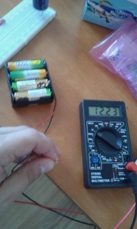
    For the sake of convenience, although I have a 16V panel, I decided to use a basket of 8 AA batteries.

    Can I connect DC to the AC heater? Will I damage the panel in the sun?

    Added after 7 [minutes]:

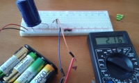
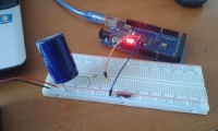
    So we have:
    (from left)

    1. Voltage source.
    2. 50V capacitor.
    3. Voltage divider (due to small losses I used large values - R1 is 986kOhm and R2 is 266kOhm).
    4. Arduino connected according to the diagram on the above-mentioned page.

    Can I connect DC to the AC heater? Will I damage the panel in the sun?

    Added after 3 [minutes]:

    Can I connect DC to the AC heater? Will I damage the panel in the sun?

    Added after 3 [minutes]:

    And my micro program was created on the principle - copy + paste.
    It works! :)

    Can I connect DC to the AC heater? Will I damage the panel in the sun?
  • #27 16626566
    gaz4
    Level 34  
    The parameters of the linked transistor allow the heater to be powered with a considerable margin. Since there is already a test "spider web", I propose to improve the PV simulation by adding a serial high-power resistor (probably 1 W is enough) between the batteries and the capacitor. Or rather two in series, because on one it will be difficult to simulate a real PV - the voltage between the connected resistors is the PV voltage (we pass it to the arduino), and on the capacitor it simulates the voltage on the heater. Such a system will simulate various types of insolation, direct connection to a battery does not allow it. If the algorithm waits for the voltage on the capacitor to increase to max, we will obtain a Uoc simulation, and we need a voltage around Umpp which is slightly lower. Therefore, the algorithm should be modified so that, regardless of the load, the measured voltage varies, for example, between 10-11V (Umpp simulation), and not approx. 12V (Uoc). If we can connect to the capacitor incandescent lamps of different power, switched on by the transistor, and the voltage at the connection point of the series resistors does not go beyond the set range, everything is OK.
  • #28 16626679
    camfly1
    Level 7  
    Gaz4, thanks for the info, I'm ordering transistors. I'll take some for testing.
    I understand that the resistor is to simulate a heater?

    Hmm. As for the program, I wanted to write so that when the voltage stops increasing (regardless of the voltage obtained) then the current is released on the heater. This would then also apply to the wind farm that I have currently constructed. (500W24V)
  • #29 16626714
    gaz4
    Level 34  
    No, the resistor does not simulate the heater, but the PV operation with less lighting (efficiency). Batteries have high efficiency, so they do not match real PV. The use of two series and voltage measurement at the point of their connection will greatly facilitate the tests - one resistor separates from the battery, the other from the load. It is worth describing two basic PV parameters:

    Open circuit voltage Uoc - this value is obtained when we do not take any energy from PV. For GS50 it is 56.1V / 62V
    Voltage at the point of maximum power Umpp - the voltage at which the PV works most efficiently. As mentioned above for the GS50 it is 38.6V / 43V.

    And now let's analyze the algorithm that waits for the maximum voltage to be obtained and only then turns on the load. If we do not consume energy, the voltage on the capacitor will reach Uoc, because until it is recharged it is the only load that consumes less and less current, up to and including zero (open circuit). The problem is that while waiting for this voltage, we cross the point where PV is most efficient, i.e. we lose energy. Thus, from the moment of exceeding Umpp to reaching Uoc, PV works with lower and lower efficiency, up to and including zero. Another issue is the voltage at which the transistor will be disconnected and the current consumption will cease. If we wait until we reach the minimum voltage, we are in exactly the same situation as direct connection to the heater. The minimum voltage will change significantly with sunlight and will be close to zero when it is cloudy. Such an algorithm will force the PV to run in an extremely inefficient manner most of the time.

    It would be most efficient to test the power released on the heater and to increase / decrease the switching voltage on an ongoing basis to make it as high as possible. However, as I wrote, the PV will work between the Umpp voltage measured under STC and NOCT conditions for most of the year. The algorithm ensuring that the transistor turns on after reaching STC and turns off at NOCT will be sufficiently effective - at the level of 90% of PV use.
  • #30 16626989
    camfly1
    Level 7  
    Gas4
    Thanks for the tips. In fact, it is worth adding resistors and rethinking the program.
    Why is it worth controlling the power dissipated by the heater? (It wouldn't be difficult)

    Here's how to drive these transistors:

    https://m.youtube.com/watch?v=vaZSQBpzcwc

    The datasheet of the linked transistor shows that after applying 5V (this is what the arduino has on the pin), it should release about 8A on the gate. What should be enough with 240V target.

Topic summary

The discussion revolves around connecting 60V photovoltaic panels in series to power a 220V AC heater using a thermostat. Key concerns include the potential damage to unconnected panels in sunlight, the wear on these panels, and the feasibility of connecting a DC voltage to an AC heater. Responses indicate that while DC can be connected to the heater, it poses risks such as thermostat burnout due to arcing when disconnecting. Suggestions include using a heater driver, capacitors, and relays to mitigate arcing issues. The conversation also explores the use of PWM controllers and the importance of matching the heater's resistance to the photovoltaic output for optimal efficiency. Various solutions, including the use of triacs, SSRs, and specific relay models, are discussed to enhance system reliability and performance.
Summary generated by the language model.
ADVERTISEMENT