logo elektroda
logo elektroda
X
logo elektroda

Manual Modular Phase Switch: DIN Rail, 20A+ Load Capacity, 4mm2 Wires, PF-431 Alternative

robertcb 8859 12
ADVERTISEMENT
Treść została przetłumaczona polish » english Zobacz oryginalną wersję tematu
  • #1 16623257
    robertcb
    Level 17  
    Is there a DIN rail switch that would do the same as automatic phase switches, e.g. PF-431, but would be manually operated, had a higher load capacity (min. 20A), did not require additional contactors and allowed for connection with 4mm2 wires?
    Or maybe one of the 3 position modular switches would be suitable for this purpose?
  • ADVERTISEMENT
  • #2 16623277
    januszbe
    Level 19  
    Enter "manual phase switch" in google
  • #3 16624037
    darecki777
    Level 13  
    Does such a switch work on the principle that when there is a voltage drop on one phase, it controls itself and switches to another with a higher voltage?
    Maybe the author can specify what device he wants to use?
  • #4 16624064
    robertcb
    Level 17  
    Yes, the switch changes phase on voltage failure or voltage drop below a certain threshold.
    I was thinking of throwing something like this into the home switchboard.
    Single-family house in the countryside, overhead line ... sometimes there is a phase missing.
    However, the automatic devices available on the market have quite a few disadvantages:
    Low load current, probably high failure rate, and apparently most devices do not have protection against phase-to-phase short-circuit.

    I suppose the device would have been ejected after the first lightning storm that struck somewhere nearby ...

    A manual switch would have no electronics and would be as reliable as an esy or differential.
  • ADVERTISEMENT
  • ADVERTISEMENT
  • #6 16624654
    robertcb
    Level 17  
    If this Hager is fit for the purpose I'm writing about, it could be.
    I do not see the switch position wiring diagram in the documentation.

    Connect the output wire to any terminal of the ammeter?
  • ADVERTISEMENT
  • #7 16625078
    mawerix123
    Level 39  
    robertcb wrote:
    I do not see the switch position wiring diagram in the documentation


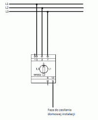
    It's hard to find some clear info, I found only a diagram from which it appears that the switch is badly described because instead of L1 L2 L3 descriptions there should be symbols 3,5,7 on which the power is supplied.

    robertcb wrote:
    Connect the output wire to any terminal of the ammeter?


    I would only check if any of the outputs marked 8 and 10 are not connected to the output of the ground symbol.
  • #8 16625530
    robertcb
    Level 17  
    mawerix123 wrote:
    I would only check if any of the outputs marked 8 and 10 are not connected to the output of the ground symbol.


    It is also not known whether it is a direct or transformer switch ...
  • #9 16625617
    mawerix123
    Level 39  
    robertcb wrote:
    It is also not known whether it is a direct switch or a transformer switch.


    It cannot have transformers inside, for the simple reason it has three IN paths, but no OUT path

    Ooo and silent like Russia, there is a connection diagram on the Russian hager website -> http://e-volta.ru/katalog/products/izmeriteln...ribory/perekljuchatel-dlja-ampermetra-20a400v
  • #10 16625748
    robertcb
    Level 17  
    mawerix123 wrote:
    Ooo and mute like Russia, there is a connection diagram on the Russian hager website -> http://e-volta.ru/katalog/products/izmeriteln...ribory/perekljuchatel-dlja-ampermetra-20a400v


    This diagram shows that the switch is connected to the coils of current transformers on the phase conductors, one end of which goes to terminals 3, 5, 7 and the other ends are connected - to terminal 1.

    There is no electrical diagram of the internal structure of this switch, as in this case:

    http://www.hager.pl/katalog-produktow/rozdzia...i-kluczykowe/sk606/47585.htm?utm_source=print

    Would such a connection of the switch be correct?

    Manual Modular Phase Switch: DIN Rail, 20A+ Load Capacity, 4mm2 Wires, PF-431 Alternative
  • #11 16626215
    cinepi
    Level 16  
    The one for 99% of transformers will not work - please analyze the diagrams of such switches manufactured by, for example, Spamel or Elektromet Dzierżoniów - they have a very complicated connection system due to the necessity to close the winding of two of the three transformers at the moment (Probably short-circuits to terminal No. 1). I suggest going to a good electrical wholesaler and ordering a connector, e.g. Spamel, with a specific program of connections in the rail version, with a cover, e.g.

    http://www.spamel.com.pl/pl/produkty/laczniki-krzywkowe/SK20_S10

    and e.g. version SK20-2.4419

    Diagrams on the website - http://www.laczniki-krzywkowe.pl/

    Best regards.
  • #12 16626851
    mawerix123
    Level 39  
    cinepi wrote:
    have a very complicated connection system due to the necessity to short-circuit the winding of two of the three transformers at the moment (probably short-circuits to terminal 1)


    You may be right, the same occurred to me today when I was wondering what the grounding switch was for.

    Thus robertcb without confirmation of operation, however, this SK603 may not be suitable.

    cinepi wrote:
    and e.g. version SK20-2.4419


    Or maybe a Sk20-2.632 switch :?: this one will be the most appropriate.
  • #13 17529271
    pkar
    Level 12  
    I tried to connect the SK603, but it was BOOM :)

    terminals:
    Z - grounding
    L1, L2, L3 - according to the description
    8, 10 - ammeter terminals
    xx - no connection

    They are combined:
    switch position 0: Z - L1 - L2 - L3 - xx - 10
    position of the switch L1: Z - xx - L2 - L3 - xx - 10 and x - L1 - xx - xx - 8 - xx
    L2 switch position: Z - L1 - xx - L3 - xx - 10 and x - xx - L2 - xx - 8 - xx
    L3 switch position: Z - L1 - L2 - xx - xx - 10 and x - xx - xx - L3--8 - xx

    But there is a simple way to remake this contraption from an ammeter switch to a phase switch :)

    Here is the procedure:
    1.Set the switch to ZERO
    2. remove the bottom cover
    3. slide out the switch assembly (no screw, ratchet, etc.)
    4.remove the jumpers between contacts 1-5 and 5-7
    5. steps 3, 2, but vice versa - it is useful to know what the setting was (from step 1).
    6.connect L1, L2, L3 according to the description on the casing, and enjoy the selected phase on terminal 8.

    More detailed information:
    The switch assembly is three switches on one axle. The contacts are numbered on the following switches: 1-4, 5-8, 9-12.
    Inputs: ground 5, L1 6, L2 2, L3 8; ammeter: 3, 7 (external terminal markings: 8, 10 respectively)
    The jumpers are factory set: 1-5, 2-4, 3-11, 5-7, 6-10, 8-12, 9-11.
    Position 0, shorted: 6-5, 8-7, 1-2.
    L1 position, shorted: 8-7, 1-2, 9-10.
    L2 position, shorted: 6-5, 8-7, 4-3.
    L3 position, shorted: 6-5, 1-2, 11-12.

    The cross-section of the jumpers (plates) is probably less than 1.5 mm2, as well as the jumpers in the form of cables (? 1.3 mm, if the caliper works well for me). Some cables are clearly thicker. I do not know how it relates to the declared 20 A.

Topic summary

The discussion revolves around the search for a manual modular phase switch that can replace automatic phase switches like the PF-431, with a minimum load capacity of 20A and compatibility with 4mm² wires. Users express concerns about the reliability of automatic switches, citing issues such as low load capacity and high failure rates. Suggestions include various models, such as the SK603 and SK20-2.4419, with discussions on their wiring diagrams and operational principles. The conversation highlights the need for a switch that can handle voltage drops and phase failures without complex electronics, emphasizing the reliability of manual switches in residential applications.
Summary generated by the language model.
ADVERTISEMENT