Dear friend, you haven't read exactly what I wrote:
1.
antek1cza wrote: it must be powered with 5V specified on the miniUSB socket (or pin on the board)
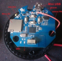
The miniUSB socket is soldered to the pins that are on the board and about these pins I wrote.
Simply put the miniUSB plug with a 5V power cable or if you don't want to have spiders (wires) you can solder the wire directly to the pins of this socket!
2.
Domen4 wrote: The miniUSB power supply must be 5V, but the pins on the board are for connecting a battery, I can't give 5V there
And that's completely right.
3.
Domen4 wrote: all I have left is a direct 3.7V Li-Ion battery supply
And I wrote about it in post no. 2 where I propose
antek1cza wrote: I propose to see what IC is included in the battery power supply-charging system, look for its data and on this basis to see how it works.
He found a colleague important information about this IC that says
Domen4 wrote: There is no minimum power supply, only a maximum 4.5V
and it's strange that he didn't follow her! And it is not about exceeding the maximum supply voltage of the integrated circuit !!!
By the way, it is a pity that the datasheet of this system was not placed here.
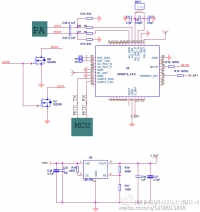
4. The system located between the USB socket, battery and IC has not been analyzed, which task is, among others, to reduce the 5V supply voltage to a level adequate to the battery charge status.
To sum up, the miniUSB socket should be 5V all the time and the battery will rise and fall depending on the degree of its discharging and charging, but certainly there is no 5V (on the battery).
5.
Domen4 wrote: However, I decided to follow the advice of Mr. @ antek1cza
He did not understand what my colleague wrote about in post no.7 (additional explanation now in p.1) and also noticed in the datasheet of the system where he writes that the maximum voltage is 4.5V.
6.
Domen4 wrote: After about five minutes it turned off without any message and unfortunately I can't start it anymore
It looks like the IC has fallen

. Maybe there is a protection in the form of a fuse (it can be similar to an SMD resistor) so it's worth seeing.
7. I propose to check all the elements that are in the battery circuit.
If you manage to restart it in no case on the IC system itself and also on the pins under which the battery is connected should not give more voltage than 4.2V (maximum voltage on the battery after charging).
8. Once you have managed to restart the speaker, I recommend following the circuits from the USB socket, battery to IC.
It will also be easier when the diagram of this part of the speaker is drawn.
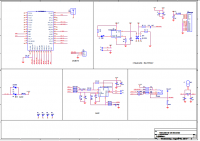
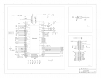
Well, unless someone has or somewhere is his whole scheme.
p. forumnot yourself
Domen4 wrote: advice of the Lord @ antek1cza
We "reign" only friends

well, unless you don't want to.


