logo elektroda
logo elektroda
X
logo elektroda

NJW1504 PLL Synthesizer: I2C Support, Setup & Troubleshooting for BASCOM Users

inspector_electro 1695 27
ADVERTISEMENT
Treść została przetłumaczona polish » english Zobacz oryginalną wersję tematu
  • #1 16651732
    inspector_electro
    Level 22  
    Hello all.

    I need to run PLJ NJW1504 synthesizer. The problem is that to run it,
    it must be initiated via the i2c bus it has. Pdf has nine pages and I have studied it. I tried to run it in the bascomie sending a datasheet bits to the chip - I think so ... well, I can not do it here.
    Could someone help me start this synthesizer wiser than me?
    I would like to take a look at PDF.
  • ADVERTISEMENT
  • #2 16651847
    excray
    Level 41  
    It looks like a fairly simple layout. So what's the problem? What do you use it for? In what frequency range will you work? Show the diagram. Show your code.
  • #3 16651938
    Anonymous
    Anonymous  
  • #4 16651947
    inspector_electro
    Level 22  
    In principle, this is the ready head in which this system sits. Has the outputs:
    1-IN
    2. The VCC-
    3. SCL-
    4-SDA
    5. GND
    6-OUT

    Head removed from the stereo sound transmitter, for wireless speakers. On the housing, he writes 863MHz. I care about 868MHz because I want to use this head
    for transmitting information from the temp / higro sensor.

    A simple program, but on the LCD I have only 255.

    Code: VB.net
    Log in, to see the code


    Added after 1 [minutes]:

      R-MIK very funny ... "you did not show the code." It is about him. You are a specialist as I suppose, and I write in the bascomie "from the jump". Give yourself sarcasm.
  • #5 16651960
    Anonymous
    Anonymous  
  • #6 16651989
    inspector_electro
    Level 22  
    Communication works because I started with the scanner. The lines are obviously tucked up, otherwise I would not find addresses 192, 194 which the scanner showed me.
    I think I can handle the rest, because the thermometer / hygrometer is ready from the weather station. With the fact that he has a 433MHz transmitter. I want instead of 433MHz to put in the head that I'm talking about. There is one IN pin in the head, and here I am going to connect the transmitter from the weather station. That is, DATA pin connect to IN head.
    The problem is just starting the head at 868MHz in BASCOM.
    The schematic is here I think I do not need. SCL and SDA lines are well connected as well as power supply. I would have to draw in ... paincie :oops:
  • #7 16651999
    Anonymous
    Anonymous  
  • #8 16652006
    inspector_electro
    Level 22  
    Well, crap. I set the range in the scanner from zero to 250 and showed me 192 and 194. I thought it works like PCF8583 or DS1307 watches. Now I'm completely stupid.
    There is only one layout, NJW1504.
  • #9 16652013
    Anonymous
    Anonymous  
  • ADVERTISEMENT
  • #10 16652019
    inspector_electro
    Level 22  
    And that's what I mean. And why do you suggest that these are write addresses? I do not understand.
    I will check the ERR variable.
  • #11 16652024
    Anonymous
    Anonymous  
  • #12 16652038
    inspector_electro
    Level 22  
    I do not have an oscilloscope or an analyzer.
    I did this:
    I set the program to display the variable ERR on the LCD. All the time shines one, and disappears under the addresses under 192 and 194. Do I understand correctly that only one of these addresses is writeable? that nothing can be read from the system?
  • #13 16652046
    excray
    Level 41  
    R-MIK wrote:
    How can one layout be seen under two addresses? You'll explain it to me because I do not know electronics, I take it for logic.

    But this type is the way it is. It is visible under two addresses.
    NJW1504 PLL Synthesizer: I2C Support, Setup & Troubleshooting for BASCOM Users
  • #14 16652071
    Anonymous
    Anonymous  
  • ADVERTISEMENT
  • #15 16652075
    inspector_electro
    Level 22  
    This note is stripped at all.
  • #16 16652087
    excray
    Level 41  
    I do not understand you. There everything is in this note what should be. I have not seen such a transparent note for a long time. Always valid means that you can always find it at this address. The second address under which you will also find it depends on the voltage at the ADRS input. Based on information shared by colleague @inspector_electro it is easy to state that this stem is compact in its module.
  • ADVERTISEMENT
  • #17 16652103
    inspector_electro
    Level 22  
    Exactly as you write. The ADRS foot is compact to ground.
    Well, what about the code? Am I making a mistake? if so, which one?
  • #18 16652144
    excray
    Level 41  
    First of all, the address is:
    192 - Write and
    193 Read,
    or
    194 Write and
    195 Read. And not like you R-192 and W-194
    In addition, the frame should look something like this:
    Code: C / C++
    Log in, to see the code

    Of course, you have to convert it to BASCOM.
  • #19 16652198
    inspector_electro
    Level 22  
    I do not know if it's good, in addition I do not understand how to number the BS.
    I do not know if instead of x in the table should be understood as 0?

    Code: VB.net
    Log in, to see the code
  • Helpful post
    #20 16652231
    excray
    Level 41  
    BS - it depends on what you have attached to these outputs. If nothing, it does not matter what you send. As for the rest, it is also rather bad. You do not want to share the schema, so it's hard to determine. I will shoot:
    My assumptions:
    - 4MHz quartz
    - the signal without an additional divider enters the system
    - we want to get 868MHz on VCO
    it comes out:
    868000000 / 8/13888 = 7812.5 = 4000000/512
    div- 13888 or:
    div_h = 54
    div_l = 64
    ctrl = 198
    bs = 0
  • #21 16652256
    Anonymous
    Anonymous  
  • #22 16652287
    inspector_electro
    Level 22  
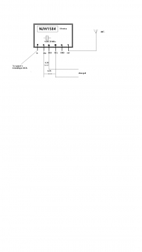
    Schemat w paincie.


    NJW1504 PLL Synthesizer: I2C Support, Setup & Troubleshooting for BASCOM Users
  • #23 16652320
    excray
    Level 41  
    I was more concerned with the schematic of this head. As I understand it, you do not have one. However, it is necessary for the correct setting of parameters. Try with the values I gave you. Alternatively, change the value of the div a little by +/- a dozen or so points.
  • #24 16652335
    inspector_electro
    Level 22  
    R-MIK write which addresses exactly because the scanner does not detect anything else. Besides, even the datasheet shows that it is 192, 194.
  • #25 16652353
    excray
    Level 41  
    Forgive me, fix. This system does not work in Read mode. Hence the situation. You can only send data to it.
  • #26 16652359
    inspector_electro
    Level 22  
    I thought so because there is no datasheet in addition as a colleague wrote earlier
    "even odd".
    I do not understand just which address if the ADRS output is connected to ground?
    192?
  • #27 16652401
    Anonymous
    Anonymous  
  • #28 16652432
    inspector_electro
    Level 22  
    I end the topic, because there are "teachers" who do not understand some, and they like to play with their grandmother. I have lost the desire for further lessons with this arrangement.

Topic summary

The discussion revolves around the setup and troubleshooting of the NJW1504 PLL synthesizer using I2C communication in BASCOM. The user initially faced difficulties in initiating the synthesizer via the I2C bus, despite studying the datasheet. Various responses highlighted potential issues such as incorrect addressing, lack of acknowledgment (ACK) signals, and the importance of checking the I2C lines. The user confirmed successful communication with the I2C scanner, identifying addresses 192 and 194. Further guidance was provided on the correct addressing for writing and reading, as well as the necessary control commands to configure the synthesizer for operation at 868MHz. The conversation emphasized the need for error checking in the code and the significance of understanding the I2C protocol for successful communication with the NJW1504.
Summary generated by the language model.
ADVERTISEMENT