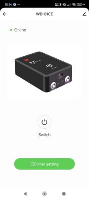
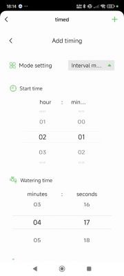
I bought the Intelligent Spray System WD-01CE (which also goes by some different names).
It's used to spray water, therefore contains a pump, a button with an LED, and a piezo module.
![[BK7231N/CBU] Intelligent Spray System WD-01CE Pump how to flash, getting bus failed [BK7231N/CBU] Intelligent Spray System WD-01CE Pump how to flash, getting bus failed](https://obrazki.elektroda.pl/3357885600_1687268115_thumb.jpg)
It's pretty easy to unscrew after removing the 4 pads over the screws.
![[BK7231N/CBU] Intelligent Spray System WD-01CE Pump how to flash, getting bus failed [BK7231N/CBU] Intelligent Spray System WD-01CE Pump how to flash, getting bus failed](https://obrazki.elektroda.pl/4647689800_1687268072_thumb.jpg)
After unscrewing, you can see the pump and the board.
![[BK7231N/CBU] Intelligent Spray System WD-01CE Pump how to flash, getting bus failed [BK7231N/CBU] Intelligent Spray System WD-01CE Pump how to flash, getting bus failed](https://obrazki.elektroda.pl/2519682900_1687268077_thumb.jpg)
To remove the board, 3 screws need to be unscrewed.
![[BK7231N/CBU] Intelligent Spray System WD-01CE Pump how to flash, getting bus failed [BK7231N/CBU] Intelligent Spray System WD-01CE Pump how to flash, getting bus failed](https://obrazki.elektroda.pl/3982023500_1687268075_thumb.jpg)
According to my research on https://developer.tuya.com/en/docs/iot/CBU-NL-module-datasheet?id=Kbaeq6j53y0yg, it uses the BK7231N chip the pins are the following:
![[BK7231N/CBU] Intelligent Spray System WD-01CE Pump how to flash, getting bus failed [BK7231N/CBU] Intelligent Spray System WD-01CE Pump how to flash, getting bus failed](https://obrazki.elektroda.pl/2296723500_1687278070_thumb.jpg)
The pinout for setup is:
P6 - Buzzer
P8 (PWM2) - Btn
P16 - REL
P20 - LED_n


