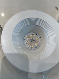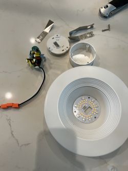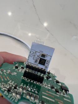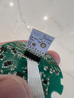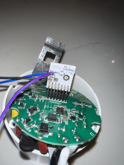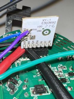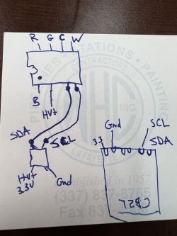
Today we will work out a completely unknown I2C protocol of the RGBCW LED controller by capturing and analyzing its packets. We will use the Sigrok logic analyzer for this, of course providing the entire system with appropriate galvanic separation because the analyzed device works on mains voltage. Then we will use the collected information to implement our own driver for these LEDs in the C language, in ours firmware . I will try to show the whole process step by step, and the fun will be interesting because the protocol we decrypt is actually not publicly documented.
The topic was created in cooperation with a colleague @DeDaMrAz. A friend did the hardware part. I took care of the command, analysis and implementation part.
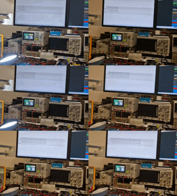
The title animation shows the lamp in question during tests; one of the monitors shows a live I2C communication capture.
Action plan
To begin with, we should make a plan of steps that we will take in this topic. Here they are, that's more or less what we need to do to implement unknown LED controller support without having its documentation:
- preliminary analysis of the inside of the device (diagram, connections)
- analysis of the batch from the WiFi module (we are able to extract Tuya configurations in JSON from it, there may be some information there)
- preparation of the station for capturing packets with a logic analyzer (ensuring galvanic isolation between the lamp and the PC)
- capturing packets during specific operations on the mobile application from the lamp (setting colors separately, dimming from 100% to 0%, brightening from 0% to 100%, switching off, etc.)
- packet analysis (how many bytes per packet, what is its format, what does a given byte mean, is there a checksum)
- implementation in C of sending packets according to the standard
- (optional) verification of sending packets still on Windows, "dry", without a device, just writing bytes to a file
- final tests of our driver implementation on a physical device (after uploading our code to the WiFi module)
- possible fixes
I will try to describe the whole process in this topic.
Subject patient
The topic concerns the so-called "smart" lamp, i.e. controlled via WiFi, via a mobile application. We try to develop our own, alternative software for such devices, fully open source, to be able to free them from the cloud and from the manufacturer's servers. Because of this, there was a whole need to analyze the protocol.
The analyzed LED lamp was presented by our user here:
https://www.elektroda.com/rtvforum/topic3985037.html
swpharis wrote:
Lampka operate się na WiFi module CB2L, na którego można wgrać OpenBeken:
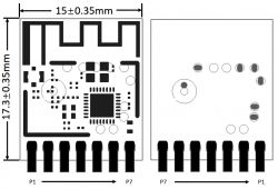
Spoiler:
| Pin number | Symbol | I/O type | Function |
| 1 | P8 | I/O | Support hardware PWM |
| 2 | P7 | I/O | Support hardware PWM |
| 3 | P6 | I/O | Support hardware PWM |
| 4 | P26 | I/O | Support hardware PWM |
| 5 | P24 | I/O | PWM hardware support |
| 6 | GND | P | Power supply reference ground |
| 7 | 3V3 | P | Power supply 3V3 |
As the name suggests, this is a module designed for Lighting, and it has only PWM pins, but are they used here? We'll see...
We started by ripping the WiFi module batch:
swpharis wrote:
The batch, more precisely the JSON configuration from Tuya, already suggested that the LED controller is not known:
Code: JSON
Of course, we ripped and decoded the batch with my tool:
https://github.com/openshwprojects/BK7231GUIFlashTool
These keys are probably the leads for the I2C GPIO:
Code: JSON
The keys below are RGBCW channel indexes (not always in order):
Code: JSON
In turn, the keys below are for setting the current for different modes of the controller, as well as some other parameters that are not very familiar to me:
Code: JSON
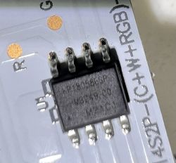
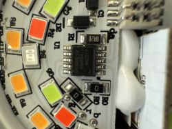
There seems to be some kind of KP58 chip inside.
This is also true:
swpharis wrote:
The presence of only two lines of communication with the simultaneous knowledge that the lamp is RGBCW (as many as five channels) already suggests that there is no PWM control here, but I2C or a similar protocol is used.
swpharis wrote:
KP18058, I managed to find residual documentation of this system. Here is an example of a schematic diagram of such a lamp:
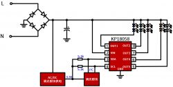
AC/DC here is a non-isolated step down converter. The "mysterious" block is the WiFi module.
So that we could learn more, a colleague from Serbia ordered the same lamp that the user had and took it to the workshop.
A slightly better scheme
After the package arrived, we decided to sketch what it looks like in practice:
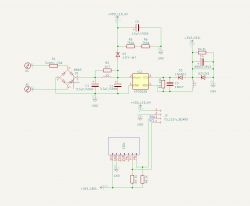
Basically everything is as I wrote. It is only worth noting that this is a 120V product, and yet the input capacitors are 400V. However, this LED capacitor is for 200V, hmm ...
But that's off topic and it doesn't really matter that this lamp is 120V - we just had to power it through a 230V/120V transformer.
Workplace and data capture
As you have probably already seen from the general scheme of the device, this lamp does not have any galvanic isolation. The WiFi module is powered by a small non-isolated step down converter and the LED controller itself is powered directly from the mains.
An additional problem here is that the product from the topic works on 120V and my friend's is 230V ... so we started with a step-down transformer:
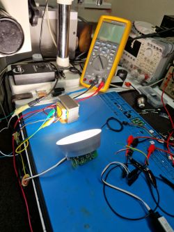
This already provides isolation, but also the isolators from Analog Devices, ADuM1201:
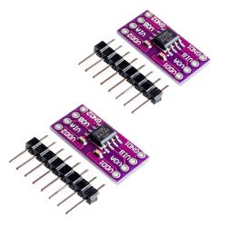
You have to connect Sigrok somehow.
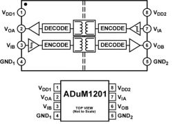
They are very cheap, only about $2 (including shipping):

Connection:
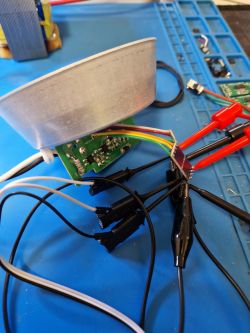
And only after them was the Sigrok analyzer connected:
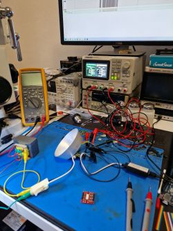
Data analysis in Pulseview
A friend performed various operations on the lamp (via a mobile application) and collected packets sent at that time. I got SR files from him with data from SCL and SDA lines:
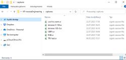
SR files can be opened with the free PulseView:

After opening, we only have the digital view of the data, which can be enlarged:
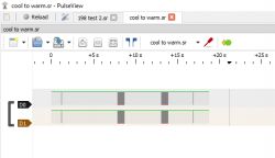
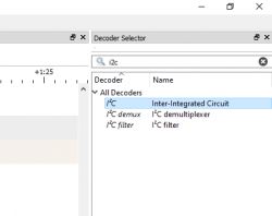
PulseView doesn't know it's I2C. You need to add the appropriate decoder:
Then you have to click into its settings and select which line is SCL and which is SDA:
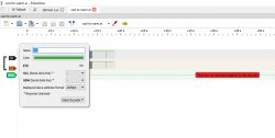
Then we will see the byte values:
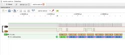
And here is the first little inconvenience - it turns out that basically it is not an I2C protocol , because here there is no address byte at the beginning, more precisely, 7 bits of the address with the R or W bit, specifying whether we are reading or writing...
The analyzer expects it and gives us "DR" that supposedly Data Read, but it's not true.
Here everything is sent by the WiFi module, the KP system only receives.
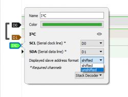
For convenience, you can disable the display of the alleged device address with the offset (because the R/W bit is the youngest) in the capture settings:
I have looked at these packages and determined that there is only one type of package which is always 14 bytes long. Some examples:


Then, in the graphics program, I compared packets from individual colors, so as to determine which bytes are responsible for them:
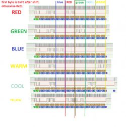
It looks like there are two bytes per color. With 5 colors (RGBCW), this is 10 bytes. There are 4 bytes left, where two are probably RGB and CW mode current limits (but I'm just guessing) and the first may be a command or operating mode.
Additionally, I saw that the first byte changes depending on whether the light is on. It seems that when the lamp is on it is 0xE1 (but not always?), and when it is off it is 0x81.
However, the very analysis of these two color bytes initially shows that their values change from 0x00 to 0x3F , implying that only the lower 6 bits of the byte are used. The values light up sequentially, suggesting that the value of one color is 12 bits. Do we have a resolution that supports 4096 different values per channel? SM2135 only has 256 values per channel and SM2235 only 1024...
Initial implementation
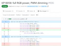
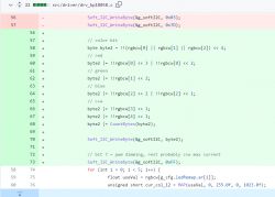
In the end I wrote something like this in C:
Code: C / C++
As I mentioned before, this is not an I2C protocol, because it does not take into account the address of their device, for this reason I had to artificially insert the first byte as a dummy address into the Soft_I2C_Start function. In addition, I think the code should be clear, in the loop I select values from the RGBCW color (ledRemap allows you to change the order of colors, because manufacturers do not have one standard), I map them from float to unsigned short (from 0 to 4095 inclusive), and then I separate them via bitwise AND (&
Dry run on Windows
My environment can also be run on Windows, I even have a built-in IoT device simulator:
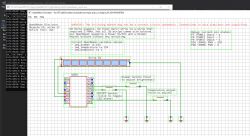
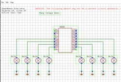
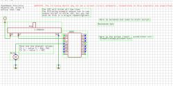
This allows me to conveniently test some things and eliminate simple errors before throwing the batch onto the device.
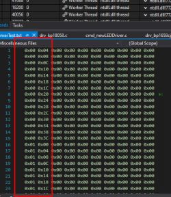
I decided, for verification, to write a simple for loop that will write the created bytes to a file, representing the color dimming process from 0 to 255.0 (the 255 looks quite unfortunate, because initially I had the colors as bytes, because the SM2135 only supports 8-bit values, but then it appeared SM2235 with 10-bit colors and changed the type to float and the range 0-255 remained):
Code: C / C++
And just handling one package:
Code: C / C++
Here is the result - does it look correct?
Changing the batch of the WiFi module
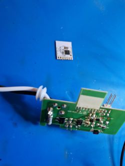
At this point, I thought we had enough data to complete the capture and change the batch on the WiFi module to OpenBeken. Then it will be easy to update the firmware remotely via OTA. You only need to upload it wired once. The module has been desoldered:
Then it hit the pin station - we connect to RX, TX, 3.3V and GND as standard:
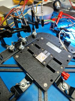
Everything according to my flasher's instructions:
https://github.com/openshwprojects/BK7231GUIFlashTool
During programming:
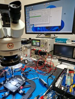
It was supposed to be so beautiful...
Finally, we ran my code on the device and got this result:
By the way, in this video below you can see live capture of I2C packets (on one of the monitors):
Dimming works, but every now and then the lamp turns off - what's wrong?
Spoiler answer. Try to solve the puzzle yourself first.
Spoiler:
After a short analysis of the collected packets, it turned out that it is not 6 bits per byte, nor is it 12 bits per color. Some bit combinations are omitted. Now the only question is why...
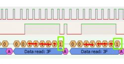
After comparing multiple packets, you can see that the lowest bit is always one when the sum of the other bits is odd, unlike zero.
This is the so-called parity bit.
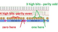
It can be said that this is the simplest, one-bit, checksum.
This bit detects upload errors and must be correctly set when uploading.
I corrected the code to count it:
Everything is working.
After a short analysis of the collected packets, it turned out that it is not 6 bits per byte, nor is it 12 bits per color. Some bit combinations are omitted. Now the only question is why...

After comparing multiple packets, you can see that the lowest bit is always one when the sum of the other bits is odd, unlike zero.
This is the so-called parity bit.

It can be said that this is the simplest, one-bit, checksum.
This bit detects upload errors and must be correctly set when uploading.
I corrected the code to count it:
Code: C / C++
Everything is working.
Summary
It was supposed to last for one evening, but it took two - all because of the issue described in the last paragraph. I didn't expect this, none of the similar controllers (SM2135, SM2235, BP1658CJ, or even BP5758D) have such a mechanism. Nevertheless, it worked out. It seems that we are the first to have support for KP18058, of course excluding device manufacturers.
As for the protocol itself - again, it deviates from the standard by lacking device addressing support, but probably it's not a problem for manufacturers. Apart from that, it resembles SM2235 a bit, meaning we have 10 bits per channel. This is slightly better than SM2135, which has only 8 bits per channel and might be noticeable for some users.
We still need to determine how the current limits are precisely set. All similar controllers allow setting current limits, separately for RGB and separately for CW. Those are likely the two bytes that always had the same value. The current limit on a given device doesn't change. Perhaps we'll have to guess and experiment. Or maybe a datasheet for this chip will appear at some point and the issue will be resolved...
In conclusion, in this way, we have yet another device liberated from the cloud, and another one of our users is satisfied.[/quote]
Cool? Ranking DIY Helpful post? Buy me a coffee.


