logo elektroda
logo elektroda
X
logo elektroda

WiFi LED RGBCW WOJ14415 with SM2135 - I2C communication protocol, interior

p.kaczmarek2 8661 33
ADVERTISEMENT
Treść została przetłumaczona polish » english Zobacz oryginalną wersję tematu
  • WiFi LED RGBCW WOJ14415 with SM2135 - I2C communication protocol, interior
    Hello, I will present here the SM2135 I2C RGBCW bulb configuration for OpenBeken. I will also provide some technical details about how the SM2135 I2C RGBCW protocol works. The bulb described here has WBLC5 module (BK7231T) and the SM2135Eh constant current LED controller.

    Purchase of WOJ14415
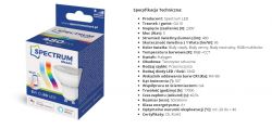
    I bought this lamp on the Polish auction portal as a result of a request from one of my users OpenBeken - I was asked to add support for the SM2135 chip.
    I found the product by searching for "GU10 5W RGB LED SPECTRUM SMART WIFI TUYA bulb", besides the title of the offer, there is also its manufacturer code - WOJ14415.
    WiFi LED RGBCW WOJ14415 with SM2135 - I2C communication protocol, interior
    I bought it along with other smart lamps, so I had free shipping.

    WiFi LED RGBCW WOJ14415 with SM2135 - I2C communication protocol, interior
    WiFi LED RGBCW WOJ14415 with SM2135 - I2C communication protocol, interior
    WiFi LED RGBCW WOJ14415 with SM2135 - I2C communication protocol, interior
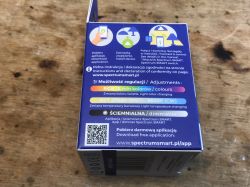
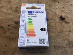
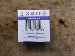
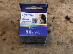
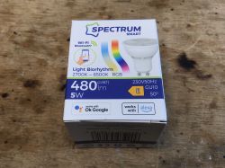
    The product arrived in a box like this:
    WiFi LED RGBCW WOJ14415 with SM2135 - I2C communication protocol, interior WiFi LED RGBCW WOJ14415 with SM2135 - I2C communication protocol, interior WiFi LED RGBCW WOJ14415 with SM2135 - I2C communication protocol, interior WiFi LED RGBCW WOJ14415 with SM2135 - I2C communication protocol, interior WiFi LED RGBCW WOJ14415 with SM2135 - I2C communication protocol, interior WiFi LED RGBCW WOJ14415 with SM2135 - I2C communication protocol, interior WiFi LED RGBCW WOJ14415 with SM2135 - I2C communication protocol, interior
    NOTE- the product is branded on the "spectrum", but it is compatible with the Tuya application!

    Teardown of WOJ14415
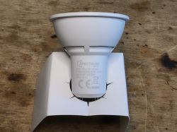
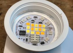
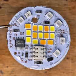
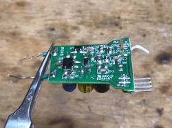
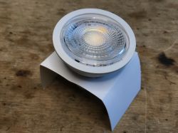
    It is quite easy to remove the plastic transparent cover. Then you can see that SM2135 is inside:
    WiFi LED RGBCW WOJ14415 with SM2135 - I2C communication protocol, interior
    WiFi LED RGBCW WOJ14415 with SM2135 - I2C communication protocol, interior WiFi LED RGBCW WOJ14415 with SM2135 - I2C communication protocol, interior
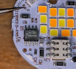
    I struggled a bit with the removal of the LED PCB. It was hard. Eventually I made a small hole on the other side and pushed it out.
    WiFi LED RGBCW WOJ14415 with SM2135 - I2C communication protocol, interior WiFi LED RGBCW WOJ14415 with SM2135 - I2C communication protocol, interior
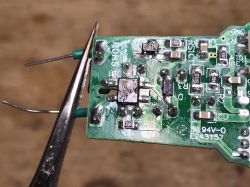
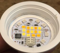
    The board pins are marked. You can see here, among others, CLK, which is the clock from I2C. The unsigned pin next to it is probably DATA, I2C data line. In addition, among others it is 3.3V (LED controller power supply), 20V (LED power supply?), ground...
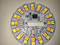
    The LEDs are separate warm, cold and colorful (RGB).
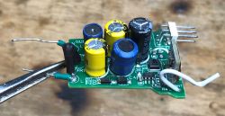
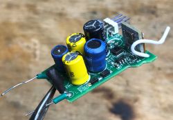
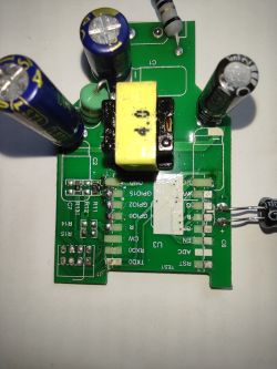
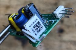
    The rest of the system with the WiFi module:
    WiFi LED RGBCW WOJ14415 with SM2135 - I2C communication protocol, interior WiFi LED RGBCW WOJ14415 with SM2135 - I2C communication protocol, interior WiFi LED RGBCW WOJ14415 with SM2135 - I2C communication protocol, interior
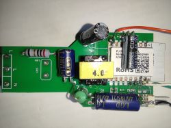
    On the board, rather the usual, a fuse resistor (FR1, Fusible Resistor), some 8HMP step down converter (with a 4R7 choke or 4.7uH), probably to power the WiFi module ...
    These 8HMP could be TP6841S6:

    WiFi LED RGBCW WOJ14415 with SM2135 - I2C communication protocol, interior
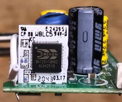
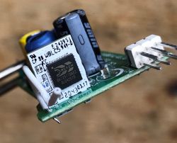
    What's under the sticker? Module with BK7231T:
    WiFi LED RGBCW WOJ14415 with SM2135 - I2C communication protocol, interior WiFi LED RGBCW WOJ14415 with SM2135 - I2C communication protocol, interior
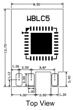
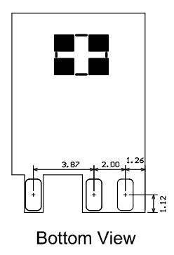
    WBLC5. Dimensions:
    WiFi LED RGBCW WOJ14415 with SM2135 - I2C communication protocol, interior WiFi LED RGBCW WOJ14415 with SM2135 - I2C communication protocol, interior
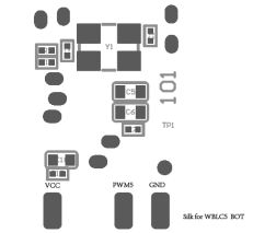
    Base pinout:
    WiFi LED RGBCW WOJ14415 with SM2135 - I2C communication protocol, interior WiFi LED RGBCW WOJ14415 with SM2135 - I2C communication protocol, interior
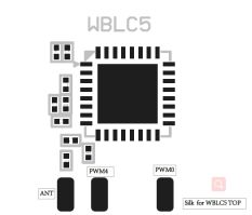
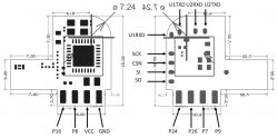
    Unfortunately, the programming pins are not described. Fortunately, I have completed the graphics for you:
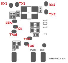
    WiFi LED RGBCW WOJ14415 with SM2135 - I2C communication protocol, interior
    You will need to solder wires to at least TX1 and RX1.
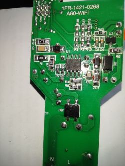
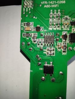
    Rest of the circuit is very usual. Fusible resistor, bridge rectifier, some other elements in SMD, most likely realized to step down power supply that converts mains to 5V or 3V or a similiar voltage (anyone can recognize the markings?):
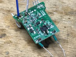
    WiFi LED RGBCW WOJ14415 with SM2135 - I2C communication protocol, interior WiFi LED RGBCW WOJ14415 with SM2135 - I2C communication protocol, interior WiFi LED RGBCW WOJ14415 with SM2135 - I2C communication protocol, interior
    I have not analyzed the PCB with power supply more deeply, it's time to focus on the SM2135.


    Five-channel I2C LED SM2135 controller
    The SM2135 controller is used to operate RGBCW lamps, i.e. it supports 5 separate channels. It is controlled via the I2C lines, two signals: DAT and CLK, are sufficient to control 5 channels. In addition, it also requires power. 5 channels + 2 lines + power supply already gives us 8 pins, so the clever manufacturer gave the ground pad on the bottom of the chip:
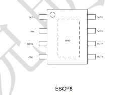
    WiFi LED RGBCW WOJ14415 with SM2135 - I2C communication protocol, interior
    SM2135 works on rectified mains voltage. No additional power supply is needed for it. An exemplary SM2135 application is presented below:
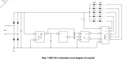
    WiFi LED RGBCW WOJ14415 with SM2135 - I2C communication protocol, interior
    I must note that I suspect the signature "AC-> DC" on the step down converter powering the microcontroller (WiFi / Bluetooth module) is wrong, because there is already DC at the input. Aside from that, everything is correct, although sometimes there is no separate LDO regulator between the step down and the MCU module, as long as the converter gives a stable 3.3V for ESP or Beken chips (or other, less frequently used).
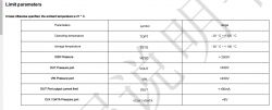
    WiFi LED RGBCW WOJ14415 with SM2135 - I2C communication protocol, interior
    I2C Communication Diagram:
    WiFi LED RGBCW WOJ14415 with SM2135 - I2C communication protocol, interior
    Here is its description from the datasheet, it should be mostly correct, except the "8byte + 1ack", it should be 8 bits and one ack. Ack signal is generated every 8 bits.
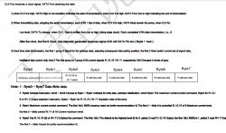
    WiFi LED RGBCW WOJ14415 with SM2135 - I2C communication protocol, interior
    The start of the transmission is indicated by the DATA transition from high to low when CLK is high.
    The end of the transmission is indicated by the DATA transition from low to high when CLK is high.
    When sending data, the DAT state should change when the clock is low.
    After 9 clock cycles, the system generates the ACK by itself, i.e. it sets the DATA pin to the low state.
    Data is sent by specifying a byte of the register address and subsequent bytes of the content (you can specify several of them).
    When it comes to registers, we have:
    - current limit (1 byte) - address 0xC0
    - RGB or CW mode (1 byte) - address 0xC1
    - color data (5 bytes, RGBCW) - address 0xC2 etc.
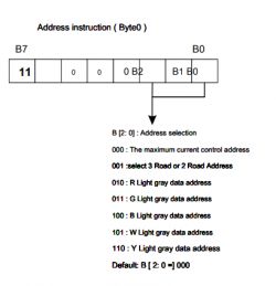
    WiFi LED RGBCW WOJ14415 with SM2135 - I2C communication protocol, interior
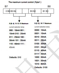
    Current Limit Values:
    WiFi LED RGBCW WOJ14415 with SM2135 - I2C communication protocol, interior
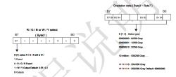
    Color values and mode selection:
    WiFi LED RGBCW WOJ14415 with SM2135 - I2C communication protocol, interior
    After sending the data (you can send different amounts of bytes, the pointer to the target address increases by itself), you should also generate a stop signal.
    Here is the entire message:
    WiFi LED RGBCW WOJ14415 with SM2135 - I2C communication protocol, interior
    I know all this may not seem very intuitive, so let's look at a practical example:
    Code: C / C++
    Log in, to see the code

    An attentive reader will see some inaccuracy here ... RGB mode but 5 colors? In practice, this is how it works that in RGB mode you can set all 5 outputs and additionally control the shades of white (cold and warm) in this way. The order of bytes from the table is changed because the LEDs were connected on this board.
    In my case, it was enough to handle all modes. I have not implemented any other methods.
    The question of I2C itself remains. You can use hardware, but you can also do it in software via simple digitalWrite and digitalRead, i.e. changing the states of digital pins in the Arduino style.
    This is exactly the implementation of popular software for ESP (based on Arduino) and I used this approach.
    (EDIT: by "popular software" I mean Tasmota, Esphome, etc, I am not referring here to Arduino Software I2C Library)
    Code: C / C++
    Log in, to see the code

    The first question from the reader should appear here - why "SetHigh" sets ... the INPUT mode? Why not just digital output with High value?
    This is because the device should be able to generate a response, the famous ACK, that is, "overwrite" the high state set by the pull up resistor (programmable) on the input pin.
    You can imagine it like a button operation, when we have a button on the input pin (between it and ground), we set the programmed pull-up and the default is state 1, but if someone presses the button, it's state 0.
    Code: C / C++
    Log in, to see the code

    Here is the procedure for writing one byte. This weird bit shift loop just iterates through the bits of a byte and then checks to see if that bit is lit in the byte we want to send.
    Then the ACK bit is received, according to what I wrote earlier, the DAT pin is set to high mode but through the input pullup (and not the output state 1), so you can read the response from the system through ReadDigitalInput. This is a simple check to see if the communication has been successful.
    It was a fairly simplified description, but I think that's enough. We already know how to set the colors in the lamps on the SM2135 and by the way we also learned a bit about the I2C itself .
    By the way, I do not see the option of selecting the device address here (i.e. it is not possible to connect many SM2135 on one bus), but probably the manufacturer did not plan it at all ...
    Full communication implementation code which I modeled on (based on digitalWrite etc):
    https://github.com/arendst/Tasmota/blob/devel...tasmota/tasmota_xlgt_light/xlgt_04_sm2135.ino

    Quick test with the Tuya application
    The Tuya application has been discussed many times, so I won't comment it here much.
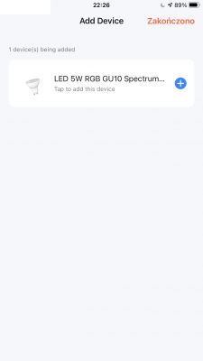
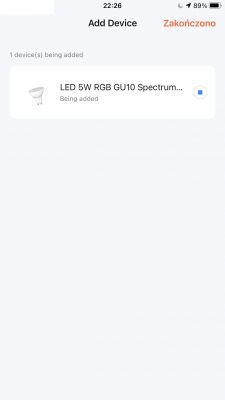
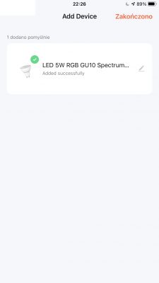
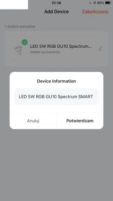
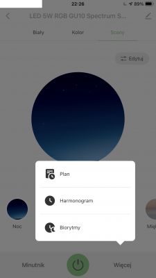
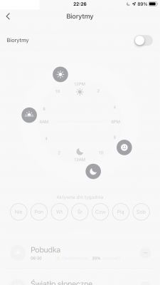
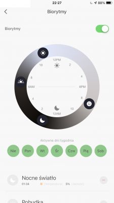
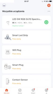
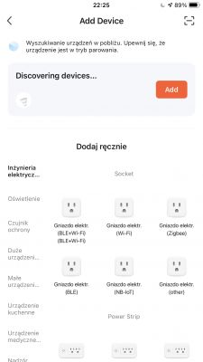
    I entered the pairing mode by repowering the lamp five times. Bluetooth had to be enabled on the phone. Pairing required my WiFi data to connect the lamp to the internet. Pairing went smoothly.
    WiFi LED RGBCW WOJ14415 with SM2135 - I2C communication protocol, interior WiFi LED RGBCW WOJ14415 with SM2135 - I2C communication protocol, interior WiFi LED RGBCW WOJ14415 with SM2135 - I2C communication protocol, interior WiFi LED RGBCW WOJ14415 with SM2135 - I2C communication protocol, interior WiFi LED RGBCW WOJ14415 with SM2135 - I2C communication protocol, interior WiFi LED RGBCW WOJ14415 with SM2135 - I2C communication protocol, interior WiFi LED RGBCW WOJ14415 with SM2135 - I2C communication protocol, interior WiFi LED RGBCW WOJ14415 with SM2135 - I2C communication protocol, interior WiFi LED RGBCW WOJ14415 with SM2135 - I2C communication protocol, interior WiFi LED RGBCW WOJ14415 with SM2135 - I2C communication protocol, interior WiFi LED RGBCW WOJ14415 with SM2135 - I2C communication protocol, interior WiFi LED RGBCW WOJ14415 with SM2135 - I2C communication protocol, interior WiFi LED RGBCW WOJ14415 with SM2135 - I2C communication protocol, interior


    SM2135 at OpenBeken
    This section is for all OBK users. First, do OpenBeken flashing as described, for example, here:
    Garden Tuya CCWFIO232PK Double Relay - BK7231T - Programming
    I performed the RESET by cutting off the power supply. In order not to overload the USB port with the current consumed by the capacitors, I used external power supply. Of course, connected via external 3.3V LDO to get stable 3.3V for WiFi module.
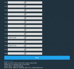
    In OpenBeken WWW panel, after doing the standard configuration, select the SM2135 I2C pins:
    WiFi LED RGBCW WOJ14415 with SM2135 - I2C communication protocol, interior
    That's basically it. From now on, you can control the lamp from Home Assistant:
    Code: YAML
    Log in, to see the code

    (the YAML configuration does not differ from the RGBCW lamp configuration based on five PWM channels on the BK7231T)
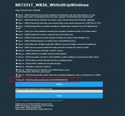
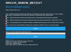
    You can also control it from the OpenBeken level, but it still requires selecting one flag in Options-> General, because without PWM pins, the system itself will not detect that it is RGBCW:
    WiFi LED RGBCW WOJ14415 with SM2135 - I2C communication protocol, interior
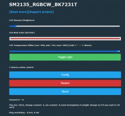
    From this moment on, you get full control on OBK WWW panel:
    WiFi LED RGBCW WOJ14415 with SM2135 - I2C communication protocol, interior
    The brightness level option is always active, but the "white temperature" and "RGB color" modes are self-exclusive. Only one can be used at time. Just like in Home Assistant.


    Order of channels in OpenBeken
    The order of RGB channels is not standardized. I found out about it thanks to the help of testers of my firmware. Therefore, the following command has been added to OpenBeken:
    
    SM2135_Map 0 1 2 3 4
    

    This command sequentially maps RGBCW channels (five channels) to SM2135 channel indexes.
    The device does not remember the mapping by itself, the command should be added to "short startup command" from Options or "autoexec.bat" from LittleFS in the new javascript panel.

    Compatible with Tasmota Device Groups
    OpenBeken is compatible with Tasmota Device Groups, which allow you to synchronize the work of many devices at the same time, as well as control a large number of devices without the use of Home Assistant. More details coming soon.

    Summary
    So SM2135 is fully functional with OpenBeken now. Thanks to good documentation as well availability of ready-made drivers there was no problem with that. Simple operations on the IO pins are available on any platform, so you only need to port the code. It is true that in the case of my OpenBeken the control is implemented a bit differently than in other systems (at the moment everything goes through RGB mode, all 5 colors), but at the moment I did not experience any problems with it.
    I would also like to thank user @rawilson for telling me to check this light. The adventure was interesting and OpenBeken got another driver.
    I attach the datasheet of the SM2135 chip.

    Cool? Ranking DIY
    Helpful post? Buy me a coffee.
    Do you have a problem with Arduino? Ask question. Visit our forum Arduino.
    About Author
    p.kaczmarek2
    Moderator Smart Home
    Offline 
    p.kaczmarek2 wrote 11844 posts with rating 9941, helped 566 times. Been with us since 2014 year.
  • ADVERTISEMENT
  • #2 20106211
    khoam
    Level 42  
    p.kaczmarek2 wrote:
    The question of I2C itself remains. You can use hardware, but you can also do it in software via simple digitalWrite and digitalRead, i.e. changing the states of digital pins in the Arduino style. This is exactly the implementation of popular software for ESP (based on Arduino) and it was this approach that I used.

    Of course, this is not true. I2C software support in Arduino Core for ESP8266 is based on interrupts and does not use digitalWrite () or digitalRead () functions - Link . However, in ESP32, the Arduino Core uses I2C hardware controllers ( Link ).
  • ADVERTISEMENT
  • #3 20106326
    p.kaczmarek2
    Moderator Smart Home
    Program support for I2C communication for SM2135 to which that sentence applies and which I discussed and showed on this topic uses the function digitalWrite and digitalRead which can be seen by anyone who wants to look for a bit more information than the one contained in the article:
    https://github.com/arendst/Tasmota/blob/devel...tasmota/tasmota_xlgt_light/xlgt_04_sm2135.ino
    Oh please, the Tasmota implementation based on digitalWrite and digitalRead .
    Anyway, I wrote about Fr. porting .

    Anyway, thank you for trying to verify my information. It boasts. If you find any real errors, write boldly. And I can correct this sentence, although I have the impression that your message results from your unawareness of how the SM2135 driver is made (sounds as if you thought that it uses the I2C software library in Arduino and not from simple digital operations defined in the same file ).

    Despite everything, you got a plus from me for reading.


    EDIT: Well, here you have the same in ESPHome:
    https://github.com/esphome/esphome/blob/dev/esphome/components/sm2135/sm2135.h
    I link so that you don't have to search.
    Code: C / C++
    Log in, to see the code
    Helpful post? Buy me a coffee.
  • #4 20106369
    khoam
    Level 42  
    p.kaczmarek2 wrote:
    although I have the impression that your message is due to your unawareness of how the SM2135 driver is implemented (sounds as if you thought it was using the I2C software library in Arduino

    There is no such thing as an I2C driver in Arduino for the SM2135. The fact that Tasmota (and a copy of this software in ESPHome [1]) has implemented bit-bang support for the SM2135 chip, mainly due to the fact that what is called "IIC" in SM2135 is not fully compatible with the standard I2C. Perhaps you haven't analyzed it very carefully a note of this arrangement and hence your unawareness about the differences between the implementation of I2C support in the Arduino Core for ESP and the so-called "IIC" in SM2135. You should not always trust Chinese Application Notes - although in this case they use CLK / DATA instead of SCL / SDA, probably out of caution.

    [1]
    Code: C / C++
    Log in, to see the code
  • #5 20106378
    p.kaczmarek2
    Moderator Smart Home
    khoam wrote:

    There is no such thing as an I2C driver in Arduino for the SM2135. It's in Tasmota

    And did I write somewhere that there is an SM2135 driver in the Arduino itself?

    As for the naming ... the official Tuya naming is I2C / IIC:
    https://github.com/TuyaInc/tuya_zigbee_sdk/bl...ee/app/light/common/src/light_driver/sm2135.c
    Code: C / C++
    Log in, to see the code


    By the way, they also have the sm16726b driver, it will be useful:
    https://github.com/TuyaInc/tuya_zigbee_sdk/bl.../app/light/common/src/light_driver/sm16726b.c
    Do you know any sm16726b product?
    Helpful post? Buy me a coffee.
  • #6 20106403
    khoam
    Level 42  
    p.kaczmarek2 wrote:
    As for naming ... Tuya's official nomenclature is I2C / IIC

    Tuya does not establish standards in terms of the I2C protocol.
  • #7 20107873
    rawilson
    Level 11  
    @ p.kaczmarek2 Thanks for taking over the driver! Of course, everything works, nothing but now wait for the creation of the device profile for tuya-cloudcutter
  • ADVERTISEMENT
  • #8 20108012
    p.kaczmarek2
    Moderator Smart Home
    You're welcome, thank Theo for blazing a trail with this driver a few years ago.

    Now I will be finalizing compatibility with the Tasmota DGR to be able to group devices on different microcontrollers (I also have LEDs on BL602, so it will be as found).
    https://tasmota.github.io/docs/Device-Groups/
    The driver will immediately start for me on the following platforms: BK7231T, BK7231N, XR809, BL602, W800 (probably also on W600 and RTL).

    I had a problem with testing this DGR driver, because somehow I couldn't get it out of spite none RGBCW LED lamps with ESP8266, although I bought them randomly (and not according to the "where is the bacon" guidelines - except for the one you indicated), but recently I ran on and I have it. It took me a long time to try. The ESP LEDs found are BKL1262 and BKL1250 ( with the date 2019 with them ).

    @rawilson, in your opinion, is it a bit more difficult to hit the Tuya product from ESP now than it was a few years ago? :)
    Helpful post? Buy me a coffee.
  • #9 20108336
    rawilson
    Level 11  
    Unfortunately, yes, I found out about it myself - but then a transplant was possible :)

    As for the bulb - I noticed that in standby mode it warms up slightly, the meter confirms it - it shows some 0.5W in idle - after connecting another piece with the original firmware, the consumption drops almost to zero. Could you check on your side if you have it too?
  • #10 20108468
    p.kaczmarek2
    Moderator Smart Home
    It is quite possible that they will put the WiFi module to sleep, especially since the SM2135 "holds" the colors after setting them, without the need for further interference from the WiFi module. This is what I will have to deal with.

    As for Tuya-cloudcutter - maybe we can make the profile ourselves?
    If you have a moment, try:
    spectrum-W...k7231t.zip Download (3.24 MB)
    English manual (partial, my notes):
    Quote:

    1. Read flash from device
    2. Decrypt with https://github.com/notkmhn/bk7231tools

    $ pipenv run python bk7231tools.py dissect_dump -e -O dump_extract_dir dump.bin

    RBL containers:
    0x10f9a: bootloader - [encoding_algorithm = NONE, size = 0xdd40]
    extracted to dump_extract_dir
    0x129f0a: app - [encoding_algorithm = NONE, size = 0xfd340]
    extracted to dump_extract_dir


    3. So you get bk7231s_dump-2022- 5-19-21-41-28_app_1.00_decrypted file
    4. Use haxomatic
    https://github.com/tuya-cloudcutter/cloudcutter-bk7231-haxomatic

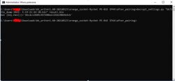
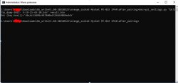
    W: \ GIT \ cloudcutter-bk7231-haxomatic> haxomatic.py "C: \ Users \ openshw \ Downloads \ bk_writer1.60-20210523 \ orange_socket-Mycket PE-01E IP44 \ after_pairing \ extracted \ bk7231s_dump-2022- 5-19- 21-41-28_app_1.00_decrypted.bin "
    WiFi LED RGBCW WOJ14415 with SM2135 - I2C communication protocol, interior
    [+] mf_cmd_process gadget address (THUMB): 0x92041
    [+] Found usable intermediate gadget at address 0x9ea48:

    5. Decrypt settings
    WiFi LED RGBCW WOJ14415 with SM2135 - I2C communication protocol, interior
    6. Command decrypt_settings.py "bk7231s_dump-2022- 5-19-21-13-22.bin" result.bin
    WiFi LED RGBCW WOJ14415 with SM2135 - I2C communication protocol, interior
    7. Open result in text viewer


    If you have a moment, do it to the point of haxomatic and show what addresses he found, if not, I'll try it in my free time ...

    If, on the other hand, haxomatic does not find (he will throw an exception), then you have to sit with Ghidra, but I will not help with that anymore.
    Helpful post? Buy me a coffee.

  • #11 20108881
    rawilson
    Level 11  
    [!] Loading and disassembling code - may take a moment
    [+] Code loaded!
    [!] Searching for post-vuln code patterns
    0[+] Found a post-vuln code pattern match!
    [+] Matched instructions: 
            0xb678c: adds r4, #0xfc
            0xb678e: ldr r3, [r4, #0x50]
            0xb6790: ldr r1, [pc, #0xb0]
            0xb6792: adds r0, r6, #0
    [+] Identified lan object register as r4
    [!] Searching for JSON object register
    [+] Identified JSON object register as r7
    [!] Searching for ty_cJSON_Parse function address
    [+] ty_cJSON_Parse address: 0xc79b8
    [!] Searching for mf_cmd_process gadget address
    [+] mf_cmd_process gadget address (THUMB): 0xad51d
    [!] Searching for a mov r0, r7 intermediate gadget
    [+] Found usable intermediate gadget at address 0xba664:
            0xba664: ldr r3, [r4]
            0xba666: adds r0, r7, #0
            0xba668: blx r3
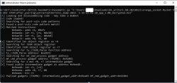
    [+] Payload gadgets (THUMB): intermediate_gadget_addr=0xba665 mf_cmd_gadget_addr=0xad51d
    
  • #12 20108924
    p.kaczmarek2
    Moderator Smart Home
    But luckily, you can easily make a profile.

    English manual continued from my notes (dirty, I hope there are no big mistakes):
    Quote:


    5. Decrypt settings
    ' WiFi LED RGBCW WOJ14415 with SM2135 - I2C communication protocol, interior
    6. Command decrypt_settings.py "bk7231s_dump-2022- 5-19-21-13-22.bin" result.bin
    WiFi LED RGBCW WOJ14415 with SM2135 - I2C communication protocol, interior
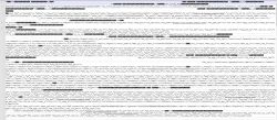
    7. Open result in text viewer
    WiFi LED RGBCW WOJ14415 with SM2135 - I2C communication protocol, interior
    8. Find schema
    Copy schema
    WiFi LED RGBCW WOJ14415 with SM2135 - I2C communication protocol, interior
    WiFi LED RGBCW WOJ14415 with SM2135 - I2C communication protocol, interior
    9. Fix the string
    10. My string (I chosen secnd one):
    [{"type": "obj", "mode": "rw", "property": {"type": "bool"}, "id": 1}, {"mode": "rw", "property ": {" min ": 0," max ": 86400," scale ": 0," step ": 1," type ":" value "}," id ": 9," type ":" obj "} , {"mode": "ro", "property": {"min": 0, "max": 50000, "scale": 3, "step": 100, "type": "value"}, "id ": 17," you: "obj"}, {"mode": "ro", "property": {"min": 0, "max": 100,000,000, "scale": 0, "step": 1, "type": "value"}, "id": 23, "type": "obj"}, {"mode": "ro", "property": {"min": 0, "max": 1,000,000,000, "scale": 0, "step": 1, "type": "value"}, "id": 24, "type": "obj"}, {"mode": "ro", "property": { "min": 0, "max": 1000000, "scale": 0, "step": 1, "type": "value"}, "id": 25, "type": "obj"}, {" mode ":" ro "," property ": {" type ":" bitmap "," maxlen ": 6}," id ": 26," type ":" obj "}]
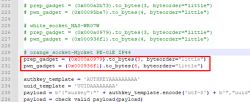
    11. Generate profile, open payload_builder.py, add here:
    WiFi LED RGBCW WOJ14415 with SM2135 - I2C communication protocol, interior
    12. Copy
    [+] mf_cmd_process gadget address (THUMB): 0x92041
    [+] Found usable intermediate gadget at address 0x9ea48:
    intermediate gadget = prep_gadget
    mf_cmd_gadget = pwn gadget
    And copied:
    WiFi LED RGBCW WOJ14415 with SM2135 - I2C communication protocol, interior
    13. Run it
    WiFi LED RGBCW WOJ14415 with SM2135 - I2C communication protocol, interior
    14. Result
    {
    "chip": "BK7231T",
    "payload": "eyJhdXprZXkiOiJBVVRIS0VZQUFBQUFBQUFBIiwidXVpZCI6IlVVSURBQUFBQUFBQSIsInBza0tleSI6IiIsInByb2RfdGVzdCI6ZmFsc2UsImFwX3NzaWQiOiJBIiwic3NpZCI6IkEiLCJ0b2tlbiI6IkFBQUFBQUFBQUFBQUFBQUFBQUFBQUFBQUFBQUFBQUFBQUFBQUFBQUFBQUFBQUFBQUFBQUFBQUFBQUFBQUFBQUFBQUFBQUFBQUjqCSJ9",
    "authkey_template": "AUTHKEYAAAAAAAAA",
    "uuid_template": "UUIDAAAAAAAA",
    "datagram_padding": "QkJCQkEgCQBBIAkAQSAJAEEgCQBBIAkAQSAJAEEgCQBBIAkAQSAJAA =="
    }
    15. In device-profiles, create directory for manufacturer and device. copy template (I copied fromk treatlife nl10)
    16. Update profile (with generated one)
    17. Open tuya.device.active.json
    18. Escape your string
    WiFi LED RGBCW WOJ14415 with SM2135 - I2C communication protocol, interior
    into
    WiFi LED RGBCW WOJ14415 with SM2135 - I2C communication protocol, interior
    19. Replace into copied active json
    WiFi LED RGBCW WOJ14415 with SM2135 - I2C communication protocol, interior
    C: \ Users \ openshw \ Downloads \ bk_writer1.60-20210523 \ orange_socket-Mycket PE-01E IP44 \ after_pairing \ extracted \ bk7231s_dump-2022- 5-19-21-41-28_app_1.00_decrypted.bin


    My additional comment - in step 8 you find a schematic describing the device, when copying it you have to be careful because you copy ASCII from binary data, from the file system and there may be sector headers that you need to skip (e.g. if you see an unnaturally interrupted string, you correct it manually)
    The schema can also be taken from another finished device in the Tuya-cloudcutter, as long as it is the same, say, device type.

    In 11 payload_builder.py you create a 'payload' string to overflow the json buffer (to overwrite addresses)

    Overall take the profile of an analogically operating lamp (RGBCW too) ready and make changes in it (maybe even the schema will match).

    Here is an example of my pull request for them, how I made a profile for the device myself:
    https://github.com/tuya-cloudcutter/tuya-cloudcutter/pull/97
    Watch yourself the diff:
    https://github.com/tuya-cloudcutter/tuya-clou...mits/41f82d20b0e4d450ec6d788441e612910740dc32

    Python scripts required:
    payload_bu..der.zip Download (2.54 kB)
    decrypt_se..ngs.zip Download (890 bytes)
    If I remember correctly, I modified decrypt_settings.py to take screenshots from BKwriter 1.60 and not from bk7231tools, because bkWriter1.60 skips the bootloader (there is a different offset).

    That's it for now, especially since I'm leaving soon and then I'll be on another machine, but you probably have everything to do a full profile. If anything, I'll try to help.

    NOTE: check each step twice and remember that there is a risk that you will lock the device if you do wrong
    Helpful post? Buy me a coffee.
  • #13 20109119
    chemik_16
    Level 26  
    oo thanks for the topic, I was just wondering why the modules dismantled from DGM bulbs give me a phase at the outputs of the esp8266.
    The LED driver is based on the SM2123, and the phase actually goes to it.
    The power supply itself looks separated from the mains, the transformer has 2 pairs of taps.
    I have already burned one by connecting GPIO4 and 5 to the modbus input of the inverter. The differential went, esp8266, max485 and the? L700?
    I have a phase on each of the esp8266 and VCC outputs, the neon lamp lights up.
    WiFi LED RGBCW WOJ14415 with SM2135 - I2C communication protocol, interior WiFi LED RGBCW WOJ14415 with SM2135 - I2C communication protocol, interior WiFi LED RGBCW WOJ14415 with SM2135 - I2C communication protocol, interior WiFi LED RGBCW WOJ14415 with SM2135 - I2C communication protocol, interior WiFi LED RGBCW WOJ14415 with SM2135 - I2C communication protocol, interior
  • #14 20110359
    rawilson
    Level 11  
    @ p.kaczmarek2 Today I will try to make a profile and test it - if it works, I will create a PR on github.
  • #15 20143599
    hode0055
    Level 2  
    Does anyone have issues with mqtt and homeassistant . for some reason the chip does not respond to any mqtt commands and homeassistant does not detect it . everything seams to be configured ok
  • ADVERTISEMENT
  • #16 20144417
    p.kaczmarek2
    Moderator Smart Home
    Hey @hode0055 , can you please provide us more information about your setup? My I2C bulb works fine with HA. Also, what do you mean by "detect it"? Currently you have to add it manually to configuration.yaml, have you tried that?
    Can you show screenshots of your configuration?
    I will try my best to help you.
    Helpful post? Buy me a coffee.
  • #17 20145727
    hode0055
    Level 2  
    Hi @p.kaczmarek2 :) Thanks for getting back so quick .
    I think I got it now . I was using the wrong configuration in in configuration.yaml . The new on is

    mqtt:
    light:
    name: "Bedside Lamp"
    rgb_command_template: "{{ '%02x%02x%02x' | format(red, green, blue)}}"
    rgb_state_topic: "bedside_lamp/led_basecolor_rgb/get"
    rgb_command_topic: "cmnd/bedside_lamp/led_basecolor_rgb"
    rgb_value_template: "{{ value[0:2]|int(base=16) }},{{ value[2:4]|int(base=16) }},{{ value[4:6]|int(base=16) }}"
    command_topic: "cmnd/bedside_lamp/led_enableAll"
    state_topic: "bedside_lamp/led_enableAll/get"
    availability_topic: "bedside_lamp/connected"
    payload_on: "1"
    payload_off: "0"
    brightness_command_topic: "cmnd/bedside_lamp/led_dimmer"
    brightness_scale: 100
    brightness_state_topic: "bedside_lamp/led_dimmer/get"
    brightness_value_template: "{{value}}"
    color_temp_command_topic: "cmnd/bedside_lamp/led_temperature"
    color_temp_state_topic: "bedside_lamp/led_temperature/get"
    #color_temp_value_template: "{{value}}"
    retain: true

    and it seams to work fine . I'll have to do some more test when I get back from work because right now the chip it's not in a light bulb .

    I was expecting mosquito to discover it automagicaly or to detect mqtt messages from my device but it's not . This is what confused me .
  • #18 20145982
    p.kaczmarek2
    Moderator Smart Home
    Ah ok, you got me worried there is some kind of bug, and as we all do know, bugs happens.

    The autodiscover is on my TODO list, right now there are things with bigger priorities.
    Helpful post? Buy me a coffee.
  • #19 20246055
    skrc1
    Level 6  
    What is the maximum current the driver cm2135 allows in the current implementation? I have greatly reduced the brightness of the CW / WW channel compared to the firmware from tuya. RGB channels - normal.
    While I'm waiting for an answer, I'll check by restoring the firmware from Tuya BK7231T and replacing wb2l with esp8266 with esphome firmware. We need to make sure that this is an OBK problem
  • #20 20246171
    p.kaczmarek2
    Moderator Smart Home
    Hello @skrc1 , the current version is using the default SM2135_20MA, but I understand that you might want to change it.

    I have added a new command for you - SM2135_Current RGBcurrent CWcurrent. For use as a 'short startup command', you can put there multiple commands with backlog, eg. backlog SM2135_Current 0x02 0x02; SM2135_Map 1 2 3 4 0,

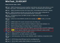
    Also enable flag - [SM2135] Use separate RGB/CW modes instead of writing all 5 values as RGB

    I didn't test it myself - please update to 1.14.37 and test and tell me if it works for you.
    https://github.com/openshwprojects/OpenBK7231T_App/releases/tag/1.14.37
    Take care, I haven't been able to test it myself yet.

    Here are current values:
    WiFi LED RGBCW WOJ14415 with SM2135 - I2C communication protocol, interior

    Please check and tell me if you need anything else. I provide daily support for my firmware and can implement the features you need.
    Helpful post? Buy me a coffee.
  • #21 20246829
    skrc1
    Level 6  
    p.kaczmarek2 wrote:
    SM2135_Current RGBcurrent CWcurrent[/b]. For use as a 'short startup command', you can put there multiple commands with backlog, eg. [b]backlog SM2135_Current 0x02 0x02

    SM2135_Current 0x07 0x02
    eq SM2135_Current CWcurrent RGBcurrent !!!
    The Best!
  • #22 20246867
    p.kaczmarek2
    Moderator Smart Home
    You might be correct indeed.

    I am also considering adding an autosave of the current values to config, so people don't have to use short startup command. What do you think?
    Helpful post? Buy me a coffee.
  • #23 20248341
    skrc1
    Level 6  
    p.kaczmarek2 wrote:
    You might be correct indeed.

    I am also considering adding an autosave of the current values to config, so people don't have to use short startup command. What do you think?

    From the user's point of view, there is not much difference. Another issue: the difficulty of finding a solution for a simple user. It is easier for him to put the necessary checkmark or select an item in the interface. Dangerous: that it can be destructive to cmd led diodes
  • #24 20299274
    rawilson
    Level 11  
    @p.kaczmarek2 is it possible to turn on / off / change the brightness smoothly as in the case of tasmot and control the LEDs via pwm (fade)?
  • #25 20299331
    p.kaczmarek2
    Moderator Smart Home
    Recently, there is a flag that allows you to enable smooth transitions between colors.
    WiFi LED RGBCW WOJ14415 with SM2135 - I2C communication protocol, interior
    Helpful post? Buy me a coffee.
  • #26 20299358
    rawilson
    Level 11  
    @p.kaczmarek2 great, it works! Is it possible (or is it planned) to configure the transition time?
  • #27 20299385
    p.kaczmarek2
    Moderator Smart Home
    I can output it to a variable somehow when I get back from an evening walk, can you use the "Short startup command"?

    EDIT: Oh no, wait... it's already derived.
    led_lerpSpeed NUMBER where the number is the number of color units (say!) per second, i.e. if you give, for example, 255, it goes from 0 to 255 in a second, if you give 128, it takes about two seconds, and if you give 500, it takes half a second....

    It's a very simple interpolation that some might even say "incorrect", but people are happy.
    Helpful post? Buy me a coffee.
  • #28 20315666
    s1dave
    Level 2  
    Hi could you help me with my LVWIT 5W 350Lm RGB Bulbs?

    WBLC9 module (BK7231T) and the SM2135Eh constant current LED controller.

    I submitted a thread but currently shows in Temporary posts so not sure if it needs approving or if it will be seen.

    I set SM2135 on P24 and P26 but I get nothing from the light
  • #29 20315739
    p.kaczmarek2
    Moderator Smart Home
    @s1dave don't worry about temporary posts, they get approved soon. I haven't seen the thread yet, but I will say this: some of the devices are using different pins for communication with SM2135 so you might need to make sure you have chosen correct ones. In case of WBLC9, you have available following signals:
    WiFi LED RGBCW WOJ14415 with SM2135 - I2C communication protocol, interior
    Pin No.SymbolI/O typeFunction
    1P9I/OHardware PWM pin, which is connected to the P9
    2P16I/OCommon I/O pin, which is connected to the P16
    3P7I/OHardware PWM pin, which is connected to the P7
    4P8I/OHardware PWM pin, which is connected to the P8
    5P26I/OHardware PWM pin, which is connected to the P26
    6VCCPPower supply pin (3.3 V)
    7P24I/OHardware PWM pin, which is connected to the P24
    8GNDPGround pin

    Are you sure that exactly P24 and P26 are used, and not some other pins?
    Helpful post? Buy me a coffee.
  • #30 20458850
    yuretskor
    Level 6  
    The spring topic, as I understand it, is the author of the sm2135 controller control driver.
    At the moment, I have connected the led module and can control it, but I noticed a feature before the flag was turned on
    WiFi LED RGBCW WOJ14415 with SM2135 - I2C communication protocol, interior
    RGB led shine brighter. As soon as I turned it on, and it became possible to control the light cold - warm, the maximum brightness of the LEDs became less.
    I also use your driver in conjunction with the driver for the sht30 sensor and they do not work together (when they are turned on together, I see that when choosing a color, the recording goes to channel 2, where the humidity readings from sht30 are currently going. Maybe somehow solve the problem together?
    Here is a link to my topic https://www.elektroda.com/rtvforum/topic3959243.html
    Also sorry for my english, I'm using a translator. And hello to you from Ukraine)

Topic summary

The discussion revolves around the configuration and functionality of the SM2135 I2C RGBCW bulb, specifically the WOJ14415 model, which utilizes the WBLC5 module (BK7231T) and the SM2135Eh constant current LED controller. Users share insights on the I2C communication protocol, highlighting differences between standard I2C and the SM2135's implementation. There are mentions of software support for the SM2135 in Arduino and Tasmota, with discussions on driver compatibility and the need for device profiles for Tuya-cloudcutter. Users also address issues related to power consumption in standby mode, the implementation of smooth transitions for LED brightness, and troubleshooting pin configurations for the SM2135. The conversation includes technical details about the driver commands and the potential for creating custom profiles for device control.
Summary generated by the language model.
ADVERTISEMENT