logo elektroda
logo elektroda
X
logo elektroda

Opening the gate with the STR-4D controller via the Roger SL2000e code lock.

ToDe 3339 7
ADVERTISEMENT
Treść została przetłumaczona polish » english Zobacz oryginalną wersję tematu
  • #1 16706660
    ToDe
    Level 8  
    Good day.
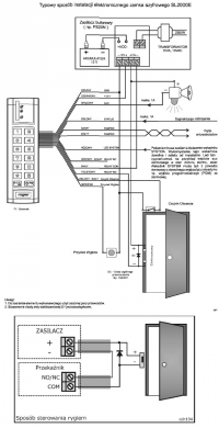
    I have a double leaf gate operating at 12V and would like to control it with a combination lock. (Roger SL2000e v 1.2)
    To be able to do this I have purchased an STR-4D roller shutter controller.

    By running the code lock according to the diagram everything works, i.e. it grants access when the code is entered.
    Also, connecting the controller in the one-button option according to the diagram, everything works as intended.

    However, I have a problem connecting the two systems. Should I use a contactor/relay?
    I am attaching the diagrams of the devices.
    Thank you in advance for your help.
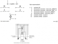

    Opening the gate with the STR-4D controller via the Roger SL2000e code lock. Opening the gate with the STR-4D controller via the Roger SL2000e code lock. .
  • ADVERTISEMENT
  • #2 16706731
    mawerix123
    Level 39  
    ToDe wrote:
    I would like to control it with a combination lock. (Roger SL2000e v 1.2)
    .

    I'm afraid that with the Roger you can only choose to open or only close, it's a device with only one relay.

    ToDe wrote:
    I have a problem with connecting the two systems though. Should I use a contactor/relay?
    .

    Write more, some time ago I was doing door strike control with intercom and access control.
  • ADVERTISEMENT
  • Helpful post
    #3 16706733
    gkwiatkowski
    CCTV and Stationary Alarms specialist
    Roger has a Relay COM/NC/NO output. In the normal state, COM is shorted to NC and NO is disconnected. When access is granted, COM disconnects from NC and short circuits to NO.
    Connect COM to terminal 7 and connect NO to plus.
  • #4 16706967
    ToDe
    Level 8  
    gkwiatkowski wrote:
    Roger has a Relay COM/NC/NO output. In the normal state, COM is shorted to NC and NO is disconnected. When access is granted, COM disconnects from NC and short circuits to NO.
    Connect COM to terminal 7 and connect NO to plus.
    .

    It worked, thank you very much. Do I need to use the diode that comes with the kit, since the lock will be connected to the controller, not the door opener?

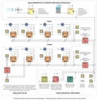
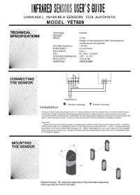
    Continuing on the subject, I would like to hook up photocells to the aforementioned kit (I have four, for two swing gate lines). I guess the easiest way would be to wire between the controller and the actuators.... but maybe there is a more refined way, maybe under the central control inputs?
    I'm attaching a diagram of the photocell and more elaborate external sensors.Opening the gate with the STR-4D controller via the Roger SL2000e code lock. Opening the gate with the STR-4D controller via the Roger SL2000e code lock.
  • ADVERTISEMENT
  • #5 16706994
    gkwiatkowski
    CCTV and Stationary Alarms specialist
    Does this door have its own control unit?
    Is there this roller shutter controller instead?
  • ADVERTISEMENT
  • #6 16707028
    ToDe
    Level 8  
    gkwiatkowski wrote:
    Does this gate have its own control panel?
    Is there this roller shutter controller instead?
    .
    There is a roller shutter controller instead of the control panel. The factory control panel was only suitable for receiving a remote control signal. There was no possibility of connecting a bell button, so I decided to remove it.
  • #7 16707182
    gkwiatkowski
    CCTV and Stationary Alarms specialist
    ToDe wrote:
    gkwiatkowski wrote:
    Does this gate have its own control panel?
    Is there this roller shutter controller instead of it?

    There is a roller shutter controller instead of the control panel. The factory control panel was only suitable for receiving a remote control signal. There was no possibility of attaching a bell button, so I decided to remove it.


    This is a bit of a dangerous solution. The roller shutter controller doesn't support photocells and you have to think a bit about connecting them, and then test the circuit in many ways to make it safe. You probably wouldn't want the gate to hurt someone.
    Looking so quickly, the photocells need to be connected to the roller shutter controller via an additional relay to the Central Up input, that is between plus and terminal 4. Then the controller should open the gate. But now I'm looking that the central control starts with a random delay of up to 1 s. That is, if someone/something gets stuck in the gate, it can still be squashed for a second before the gate stops and starts to open.
    I strongly urge you to buy a dedicated gate controller. No problems with connecting photocells, programmed to react appropriately to the appearance of an obstacle, tested, safe.

    What was the original control panel on this gate?

    Added after 2 [minutes]: .

    ToDe wrote:
    .

    It worked, thank you very much. Do I need to use the diode that comes with the kit, since the lock will be connected to the controller, not the door opener?
    .

    The diode will then be unnecessary.
  • #8 16711957
    ToDe
    Level 8  
    Thanks for the tips, I will check in practice how it works and let you know.
    I'll also check what the control panel in the kit was, but there was no way to hook up photocells in it either.
ADVERTISEMENT