Elektroda.com
Elektroda.com
X

Arduino nano - first run, test, opinion.

TechEkspert 13293 24
This content has been translated flag-pl » flag-en View the original version here.
  • Arduino nano - first run, test, opinion.
    The Arduino nano module equipped with a microcontroller will soon appear on elektroda.pl ATMega328P clocked with a 16MHz quartz resonator, power supply with 5V from the USB port. The board is equipped with a USB UART converter, which facilitates placing the program from the Arduino environment. On the board, there are LEDs informing about the presence of power, activity on the RX / TX lines of the UART interface and the LED connected to the D13 pin. The microcontroller is powered by 5V and the board ports operate at such logic levels, it should be remembered that some modules tolerate only 0-3.3V on the interfaces. The Arduino nano board also has a 5V stabilizer (power input> 5V on the VIN pin), there is also a reset button. Connector AND SP allows you to place the program using the programmer, using ISP, you can even opt out of the bootloader or the Arduino environment and send the compiled code written in, for example, Atmel Studio 7.0. Through the ISP connector we can change the microcontroller settings (fusebits). USB UART converter is CH340 and if there is no driver in the system, they are available on the manufacturer's website:
    information about CH340
    documentation
    Windows drivers
    Linux drivers
    If the driver is installed correctly, a new serial COM port will appear in the system after connecting the module.

    We start the integration with the board by downloading the Arduino environment, the current version is 1.8.4
    We create a new program (sketch) and select the Arduino nano board:
    Tools-> Board-> Arduino nano
    Next:
    Tools-> Port-> and select the COM port on which is the board connected to the USB.

    As an example, we will move from the banal LED flashing to controlling the LED to the rhythm of the music.

    LED flashing.
    To check if everything is working properly, we will run the program which will flash the LED on the board (D13) and the LED connected with the anode to the D2 terminal, the LED cathode through the 220R resistor to ground (GND) on the contact plate. The LED state can be changed with digitalWrite (pin_number, LOW / HIGH)
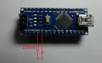
    Arduino nano - first run, test, opinion.
    We compile and upload the program:
    Code: c
    Log in, to see the code


    As a result, we have flashing LEDs and the flashing speed can be changed by modifying the delay value:
    delay (1000);
    [movie: 88fd792b6d] https://filmy.elektroda.pl/18_1505668055.mp4 [/ movie: 88fd792b6d]

    Flashing LED with a change in brightness.
    To change the brightness of the LED while flashing, we can use PWM with analogWrite (pin_number, value 0-255).

    We connect the LED to D3 and through the 220R resistor to ground, compile and upload a simple program:
    Code: c
    Log in, to see the code


    As a result, we obtain smooth changes in the brightness of the LED light.
    [movie: 88fd792b6d] https://filmy.elektroda.pl/16_1505668363.mp4 [/ movie: 88fd792b6d]

    Flashing RGB LED.
    Connect the LED GRB cathode to D3, D5, D6 through 220R resistors, and the common anode to + 5V and with PWM we can smoothly mix the light colors. As the LED is connected with the anode to + 5V, the PWM 255 filling will mean the LED will go out.
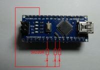
    Arduino nano - first run, test, opinion.
    Code: c
    Log in, to see the code


    [movie: 88fd792b6d] https://filmy.elektroda.pl/5_1505668880.mp4 [/ movie: 88fd792b6d]

    LED line that reacts to sound.
    This time, we will connect the LEDs through resistors to GND to the D2, D3, D4, D5, D6, D7, D8, D9 pins and simulate the operation of the LED line responding to the signal given to the A0 input. We will use sample music to test the program: Link
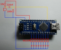
    Arduino nano - first run, test, opinion.
    Code: c
    Log in, to see the code


    [movie: 88fd792b6d] https://filmy.elektroda.pl/53_1505669237.mp4 [/ movie: 88fd792b6d]

    The miniature Arduino nano module can be useful for many experimental and prototype systems, while numerous examples and libraries will facilitate the implementation of your ideas. Here are two examples of using Arduino to record data on an SD card and in the built-in EEPROM memory:
    Weekly measurement of mains voltage frequency - experiment.
    Heart rate recording while sleeping - Arduino nano.

    I encourage you to experiment with sample program codes, it can be quite an interesting tool in sound visualization FFT especially on the ESP8266 or ESP32 platform supporting Arduino and equipped with a faster processor and more RAM, it is worth taking a look at: FFT in practice using ESP32 and Arduino. Modules with ESP8266 have already appeared in the elektroda.pl gadgets, it is worth checking if they may have appeared again.

    What is your idea of using Arduino nano?
    Arduino nano - first run, test, opinion.

    Cool? Ranking DIY
    About Author
    TechEkspert
    Editor
    Offline 
    TechEkspert wrote 4929 posts with rating 4029, helped 12 times. Been with us since 2014 year.
  • #2
    pawelr98
    Level 39  
    One more useful information.

    The board can be powered with voltage up to 15V.

    As you can see on board we have AMS1117-5.0 which is a 5V LDO stabilizer.

    The input of this stabilizer is led out to one of the pins marked as Vin (right next to ISP).

    I have an identical Nano from China. The cost is PLN 10.5.
  • #3
    lukaszd82
    Level 30  
    Hello,
    AMS1117-5.0 has a power supply up to 15V according to the catalog note. In addition, I downloaded such nano from China for PLN 6.5-7 when buying individual pieces. ($ 1.93 Link . I bought for $ 1.78 ...
  • #4
    TechEkspert
    Editor
    Thank you for the hint, I added information about the VIN input that allows powering with> 5V.
  • #5
    lukaszd82
    Level 30  
    as I remember correctly, this board should be supplied with Vin 6.5-15V so that this stabilizer gives 5V.
  • #6
    pawelr98
    Level 39  
    lukaszd82 wrote:
    Hello,
    AMS1117-5.0 has a power supply up to 15V according to the catalog note.


    I have already corrected my post so that there is no confusion, I confused with the LM1117 which has 20V.

    As for applications, the Arduino can even be used as a primitive oscilloscope. Project to be found in google.

    Very poor band and maximum 5V input, but for a few zlotys you won't get anything better.

    I am going to use my arduino as a thyristor driver.

    Flash point calculation using numerical methods.

    Project more as a practical use of knowledge from studies.
  • #7
    rafcio_21
    Level 29  
    I am going to use the nano in conjunction with the M590 modem to control via sms and additionally sms notification from the ca10 satellite alarm. Currently testing and polishing the code.
  • #8
    lukaszd82
    Level 30  
    You can get something better: STM32F103C8T6. Performance and possibilities much more. The price is about PLN 6.50. on Ali, you can program with Arduino IDE. I'm just testing. I ordered 2 pieces. Performance up to 10x greater than the Arduino nano on the Atmega32. Sometimes the downside is the logic at 3.3v and a little less libraries, but you have to learn new things. All the more so at a comparable price.
  • #9
    tronics
    Level 38  
    I have a MySensors node with NRF24L01 + (and HC-SR501 + dimmer of 5050 led strips to implement fade in and fade out to avoid dazzling at night, another node with RGB and MFRC522). On STM32F103, maybe the libraries would start working after some modifications, so it's worth checking if I find a good quality source of such modules.
  • #10
    TechEkspert
    Editor
    @ pawelr98 the effects of thyristor triggering experiments should be put in DIY or articles.

    @ lukaszd82 it would be good to present the achieved results on STM, good variety from Microchip ARM and AVR, logic 3.3 for example is an advantage for me - easy connection of SD card, TFT / OLED / LCD displays and many sensors.

    @tronics this LED dimer is some specialized PWM controlled by eg SPI, did you use ATMega PWM outputs?
  • #11
    tronics
    Level 38  
    @TechEkspert - it is a matter of how to configure, if we want nice hardware PWM then PWM outputs, if we do not mind that sometimes something will not work smoothly, then on any pin you can have software PWM in Arduino. The actuator is IRLZ44N, so even quite long straps can be used. This is for night / winter lighting of the corridor and stairs - sudden switching on at 100% when the eyes are adapted to the darkness is not nice, and the meter long pieces of tape behind the milky cover light up nicely gradually in sequence (depending on whether we are entering or descending).
  • #12
    pawelr98
    Level 39  
    TechEkspert wrote:
    @ pawelr98 the effects of thyristor triggering experiments should be put in DIY or articles.


    If I get the contact plate, I will check it. I have an oscilloscope, so the circuit operation documentation will not cause any problems. Ot measuring the voltage from the voltage divider and then calculating the ignition point on this basis in order to obtain the appropriate peak voltage / power. Ignition at the given peak voltage will save some on transformers.

    I still have a Raspberry Pi3 but I bought an arduino because of the built-in analog-to-digital converter and the possibility of programming without the operating system.

    I have already written simple C programs on Raspberry Pi 3, but you still have to run it in the operating system.
    Usually, I connect via SSH via Wi-Fi and use my PC to run programs.

    And yes, I can do it autonomously.

    In addition, a possible "accident" will not hurt so much (financially). Arduino costs PLN 10 or less, Raspberry Pi3 around PLN 160.

    For me, converting logic from 5V to 3.3V is not a big problem. 3 diodes 1N4148 or other pulsed silicon (4 if the diode voltage drop is too low) in both directions and no problem.
  • #13
    krzbor
    Level 25  
    I think the Arduino Pro Mini is a better solution. On Ali for $ 1.45. There are 16MHz 5V and 8MHz 3.3V versions. This Arduino does not have a USB, it can be programmed more conveniently through a converter based on FTDI (ft232). It is also smaller, of course.
  • #14
    TechEkspert
    Editor
    @krzbor Arduino mini pro is very good for certain applications, it is easy to get low power consumption (additionally eliminating the LED power), in the 8MHz version it works with 3.3V which allows you to connect directly devices with 3.3V logic for me it simplifies the connection of e.g. SD cards, OLED cards etc. .
    However, each solution has its own application, e.g. Arduino nano has a built-in USB UART converter, which eliminates the need to connect additional external devices, a regular USB cable is enough and we already have power and communication, for portable test systems, power supply from USB / power bank is an advantage . The disadvantage may be the 16MHz clock because officially it requires a 5V power supply for stable operation, of course you can supply 3.3V and, for example, change the clock to an internal 8MHz RC generator by connecting to the ISP connector, but it is more convenient for experiments to have Arduino nano 5V 16MHz and mini pro 3.3V 8MHz .
  • #16
    pawelr98
    Level 39  
    One small piece of advice for those who are going to use the ADC built into the board.

    There are several modes of operation.

    Default - enter analogReference (DEFAULT) or enter nothing
    In this mode, the + 5V power rail is used as the reference voltage.

    When powered by USB, the voltage could drop to about 4.7V. The arduino itself still works normally, but the rail floating did not allow for any stable measurement.
    If we have a relatively stable + 5V power supply (for example using a soldered AMS1117), you can use it from poverty.

    Fortunately, the Atmega 328P has a built-in reference voltage.
    It is 1.1V and is activated by the analogReference (INTERNAL) command.

    In this case, DO NOT connect any other voltage to this pin because a short circuit will damage the system.

    The last option is analogReference (EXTERNAL). In this case, we give the reference voltage to the REF pin. Voltage must be in the 0-5V fork.

    One last piece of advice. For testing, I bought a contact plate for a few zlotys.

    If someone is going to take measurements on it, I advise against it.

    1.1V was too low for me, so I used the 1431 (2.5V +- 0.4%, the more precise TL431). At the board, the reference voltage was floating by up to 100mV.

    As a solution, I soldered the 300? resistor between + 5V and the REF pin permanently.
    As a result, the power to the reference system is stable. Still floating minimum, but the sample AA battery voltage reading changes by a maximum of one unit (reference voltage divided by 1024).
    For this, connect a capacitor between the ground and the REF pin.

    The ADC itself appears to be quite accurate.

    For those who do not like to modify, I strongly recommend using an internal voltage source. Less work, but the ADC input range is limited to 1.1V.
  • #17
    TechEkspert
    Editor
    Thanks for the hint, I used analogReference (INTERNAL) in the examples with the microphone signal, the ADC 0-1.1V operating range allowed for greater sensitivity of the circuit, and in the test circuit, I didn't have to worry about overloading.
    But for example in the example with the heart rate monitor although the amplitude of the useful signal was small, the DC component was from 0V to + supply ... Although the resolution at Vref 5V turned out to be sufficient, a simple trick with removing the DC component and using Vref 1.1V could improve the sensitivity of the circuit.
  • #18
    piotr_wik
    Level 10  
    I need something else to program, is the set from the store all that is necessary?
  • #19
    pawelr98
    Level 39  
    piotr_wik wrote:
    I need something else to program, is the set from the store all that is necessary?

    The kit includes everything you need.

    You connect the Arduino to the computer using the included USB cable.
    Then you install the driver (provided in the first post of this topic).
    You run the Arduino IDE, select the appropriate COM port (the port number can be read in the device manager) and you can program.
  • #20
    pikarel
    Level 37  
    With the current version of Arduino 1.8.9, to load the compilation to Nano, select the processor:
    ATmega328P (OldBootloader).
  • #21
    dany1002
    Level 10  
    Hello. I know it's probably a stupid question, but I'm taking my first steps ;-) is it possible to rewrite the sketch from arduino uno to arduino nano? Specifically, I mean the modification of the ambilight sketch for TV on leds 2812b I have a sketch under UNO and I wanted to convert it into nano. Is someone something? Thanks and sory for probably a stupid question. More specifically from this link https: //drive.google.com/file/d/0BxKP ...
  • #22
    Karaczan
    Level 41  
    You don't have to do anything. Both boards have the same processor.
  • #23
    pustan
    Level 19  
    Colleagues, help me.

    Arduino nano. Downloaded arduino environment. Installed. Selected board, processor, port. The first program selected, i.e. LED blinking. Compiled, uploaded to uno. There are no errors. And what's next ? I have programmed and programmed AVRs, I start PICe here with a nano board. There was always a start button, a run button or a power supply button.
    I looked through many descriptions of how to program uno. One sentence is missing everywhere.
    Programmed processor and what's next. At this point, the diode is blinking, if something else needs to be done to make it move. I can leave the environment and the LED will blink. If I give the power supply not via USB and the scheld with an external power supply, will it start and the LED will blink?
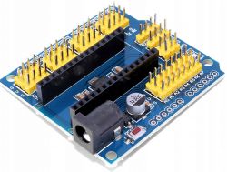
    My plate for nano.

    Arduino nano - first run, test, opinion.


    Best regards.
  • #24
    tronics
    Level 38  
    If you know how a microcontroller works, this is at least a strange question. The Arduino environment connects to the board for 2 purposes, when it uses the bootloader to load the program (i.e. after loading, it does NOT control anything) and when we turn on the terminal on the selected COM port (and the microcontroller is programmed to send or receive something and interpret it) . Hence, after programming, you can disable the IDE and it will work. You can unplug the usb power, plug it in and it will still work. You can give external power to VIN and it will work too. It would be practically pointless to act otherwise.
  • #25
    pustan
    Level 19  
    Thanks for the answer.

    Although, as I wrote, I know the rules for AVRs and PICs, the aurdino environment is new to me. Still, the case is very cool. I have already answered the questions that I asked. I wrote a post at night. After writing further, I explored the magic of programming and description for the first run. In the morning I only figured out what it was about. Aeduino WORKS !!!.
    I was suggesting the diode attached to the PCB pins. She still doesn't shine even though she is operational. But the diode soldered in the NANO works and can be controlled by software. Now I just have to find a list for this expansion board on the net.