FAQ
TL;DR: If your Kraft & Dele IGBT250 lights the switch but shows no fan or display, check for ~330–340 V DC on the main capacitors; "damaged 24V DC auxiliary converter" is a common root cause. [Elektroda, master250, post #16815388]
Why it matters: This quick path isolates mains, soft‑start, or 24 V aux faults so you can decide repair vs. service.
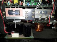
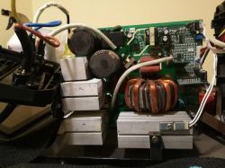
- Typical bulk DC after the bridge: ~320–340 V on the main capacitors when mains and rectifier are OK. [Elektroda, skalsky5000, post #16811289]
- Loss of 24 V auxiliary supply stops the fan, display, and control logic. [Elektroda, master250, post #16815388]
- Soft‑start path uses a posistor/NTC and a relay; faults here can block capacitor charging. [Elektroda, star_vad, post #17395471]
- Known failures: burnt auxiliary transformer primary terminals or its current‑sense resistor. [Elektroda, stasiekb100, post #16821789]
- Some versions use a ~50 Ω, ≥5 W soft‑start resistor; open circuit = no DC on caps. [Elektroda, stasiekb100, post #17385525]
Quick Facts
- Typical bulk DC after the bridge: ~320–340 V on the main capacitors when mains and rectifier are OK. [Elektroda, skalsky5000, post #16811289]
- Loss of 24 V auxiliary supply stops the fan, display, and control logic. [Elektroda, master250, post #16815388]
- Soft‑start path uses a posistor/NTC and a relay; faults here can block capacitor charging. [Elektroda, star_vad, post #17395471]
- Known failures: burnt auxiliary transformer primary terminals or its current‑sense resistor. [Elektroda, stasiekb100, post #16821789]
- Some versions use a ~50 Ω, ≥5 W soft‑start resistor; open circuit = no DC on caps. [Elektroda, stasiekb100, post #17385525]
My switch lights up but there’s no fan or display—what should I check first?
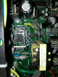
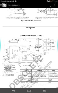
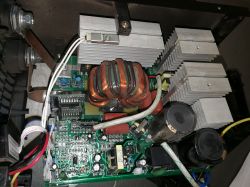
Verify ~330–340 V DC across the bulk capacitors, then confirm the 330 V reaches the control board. Next, check the 24 V auxiliary supply around the UC3845 controller Vcc. "You probably have a damaged 24 V DC auxiliary converter." [Elektroda, master250, post #16815388]
Where is the fuse on the Kraft & Dele IGBT250, or is there one?
These welders often rely on a soft‑start path (posistor/NTC plus relay) and the mains input protection rather than a visible PCB fuse. A failed soft‑start can mimic a blown fuse by preventing capacitor charging and system start. [Elektroda, star_vad, post #17395471]
How do I locate the inverter driver IC (UC3845) on the top board?
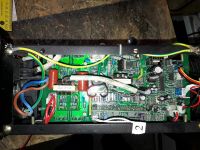
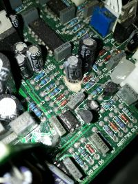
Find the 8‑pin vertical IC closest to the yellow pulse transformer of the auxiliary converter. That is the driver/controller you’ll measure for Vcc to confirm aux supply start‑up. [Elektroda, master250, post #16821924]
I measure 340 V on all three capacitors—what does that tell me?
Your rectifier and primary DC bus are alive. Focus on the auxiliary 24 V converter and its controller Vcc, because the fan and display depend on that rail to run. [Elektroda, tbilski, post #16812616]
230 V reaches the board but the capacitors have no voltage—what’s likely open?
Check the soft‑start element. Some versions use a ~50 Ω, ≥5 W resistor; if it opens, the bulk capacitors won’t charge and the relay never takes over. [Elektroda, stasiekb100, post #17385525]
What soft‑start parts should I test on this welder?
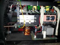
Test the posistor/NTC (green disk near the relay), the start‑up path to the capacitors, and relay operation. If the low‑power supply fails, the relay may never energize. [Elektroda, star_vad, post #17395471]
Known failure: why do auxiliary transformer primary pins burn on some units?
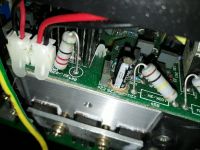
Heat and mechanical stress can carbonize or crack the primary pins or the series current‑sense resistor. That interrupts the 24 V supply and halts the control electronics. Inspect and rework those joints. [Elektroda, stasiekb100, post #16821789]
What voltage should I see on the relay coil that feeds the fan and logic?
Expect approximately 24 V at the relay coil in this design. If it’s missing, the auxiliary converter or its start‑up path is down, and the unit stays inert. [Elektroda, Pawu0206, post #17384366]
How do I safely measure the key voltages without an oscilloscope?
- Discharge and then meter DC across the bulk capacitors for ~320–340 V.
- Confirm that high‑voltage DC reaches the control board.
- Measure UC3845 Vcc for start‑up to validate the 24 V auxiliary supply. [Elektroda, skalsky5000, post #16811289]
The welder fell over and then stopped—what extra should I inspect?
Look for cracked solder at the auxiliary transformer, a broken posistor, or a faulty mains switch. Also check IGBTs for shorts; impact can precipitate failures. [Elektroda, star_vad, post #17395471]
Does a lit power switch guarantee the control electronics are working?
No. The lamp only shows mains reach the switch. With a dead 24 V rail, the fan and display remain off despite the illuminated switch. [Elektroda, master250, post #16815388]
What’s the quick diagnosis path when there’s 330 V on the bus but no life?
Treat it as an auxiliary‑supply failure. Measure UC3845 Vcc, inspect its start‑up resistor, and check the auxiliary transformer and current‑sense parts. [Elektroda, master250, post #16815388]
What are the two sealed precision potentiometers near the display connector?
This thread does not confirm their function. They are likely factory calibrations; avoid adjustment without documentation or a schematic. [Elektroda, Raku025, post #19322642]
Can I get a schematic for this exact board revision?
A specific schematic was not provided here. Moderation suggested opening a new topic for different board versions or issues to obtain targeted documentation. [Elektroda, Krzysztof Reszka, post #17384585]
Edge case: I see 330 V on caps, relay clicks, but it still won’t start—why?
The auxiliary transformer primary joints or its current‑sense resistor may be heat‑damaged. Repairing those restores the 24 V rail and start‑up. [Elektroda, stasiekb100, post #16821789]
