logo elektroda
logo elektroda
X
logo elektroda

MGSI-200 IGBT Magnum Welder: No Response to Potentiometer, Need Control Diagram

bokun 22863 12
ADVERTISEMENT
Treść została przetłumaczona polish » english Zobacz oryginalną wersję tematu
  • #1 16462919
    bokun
    Level 11  
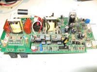
    As in the topic, the welder turns on the 15 V power supply, there is no response to the potentiometer. On the forum I found a diagram very similar to my system, but only the main one, I lack the control part, the welding machine has a hot start and anti-stik. My measurements show that I do not have voltage for the IGBT control transformer. On the control board, apart from the integrated circuits, there is such a bridge composed of IRFZ24 and IRF9Z24, it is possible that they control the operation of the steering transformer.
    Any advice or a diagram of such a welding machine? The board is removed from the heat sinks.
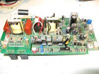
    MGSI-200 IGBT Magnum Welder: No Response to Potentiometer, Need Control Diagram MGSI-200 IGBT Magnum Welder: No Response to Potentiometer, Need Control Diagram
  • ADVERTISEMENT
  • #2 16463002
    SQ5AZP
    Level 33  
    Take accurate photos of the plates of this welder and blend.
  • #3 16509569
    panstalin2
    Level 20  
    It is possible to replace it in the upper right corner of CA3140.
  • #4 16517913
    bokun
    Level 11  
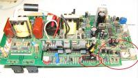
    For a better overview, I have included descriptions of the scalers in the photo. The stabilizers are operational. LM358 with the potentiometer plug replaced, IFRZ24 checked. After removing the plug (bottom right) from the welder's output, the output voltage increases from about 9V to 57V, but the minimum current barely sparks.
    MGSI-200 IGBT Magnum Welder: No Response to Potentiometer, Need Control Diagram
  • ADVERTISEMENT
  • #6 16519899
    bokun
    Level 11  
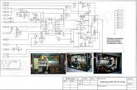
    A good diagram, a good link, if you have a diagram and you can still rummage with tension. I also walked on these Russian sides. The main diagram is identical to this figure only stronger transistors and less. and as for the chip, you mean on the vertical board you have to remove it first.
    MGSI-200 IGBT Magnum Welder: No Response to Potentiometer, Need Control Diagram
  • ADVERTISEMENT
  • #7 16520299
    panstalin2
    Level 20  
    MGSI-200 IGBT Magnum Welder: No Response to Potentiometer, Need Control Diagram

    Check everything carefully here:
    MGSI-200 IGBT Magnum Welder: No Response to Potentiometer, Need Control Diagram
  • #8 18644128
    lecho5law
    Level 8  
    Hello, I have a similar problem. The welder always welds at maximum current, no adjustment.
    On the display, the value of current changes when the potentiometer changes.
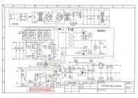
    I checked all voltages according to the diagram below and everything is correct.
    The question is what else should be checked and measured?
    MGSI-200 IGBT Magnum Welder: No Response to Potentiometer, Need Control Diagram
    https://obrazki.elektroda.pl/3415508400_1496903282.jpg
    Below are photos of the device

    https://obrazki.elektroda.pl/8453558600_1584450081.jpg
    https://obrazki.elektroda.pl/1873687000_1584450080.jpg
    https://obrazki.elektroda.pl/4164701700_1584450079.jpg
  • #9 18645494
    SQ5AZP
    Level 33  
    After all, the error amplifier circuit must receive a signal from the current transformer!
    When the transformer is damaged, signal forming elements, paths to op-amp. - the effect will be exactly as described, and the amplifier's voltages will be within 10-15% tolerance! load the output with a 2? / 800W resistor and you can easily feel where the problem lies with the oscilloscope.
  • ADVERTISEMENT
  • #10 18847488
    Wacko123
    Level 2  
    Hello, digging up the topic of the welding machine, I have a problem with the welder and I have a burned out transformer on the plate type EEL25 200 12 22 22 CE, looking at the diagram above at my friend, it is a T2 transformer, or someone is able to offer something to replace or solve it in some other way way? because searching for it is only available in Chinese stores
  • #11 19158243
    ukixx
    Level 21  
    Wacko123 wrote:
    Hello, digging up the topic of the welding machine, I have a problem with the welder and I have a burned transformer on the plate type EEL25 200 12 22 22 CE

    EEL25 are the dimensions of the core, the remaining numbers i.e. 200, 12, 22, 22 are the numbers of turns. The primary winding has 200, feedback is 12, and those after 22 are from +/- 24V. Probably it will be faster to unstick the core and rewind it, or you can put in two 24V power supplies.
  • #12 19917073
    Loveths Mannongol
    Level 2  
    bokun wrote:
    A good diagram, a good link, if you have a diagram and you can still rummage with tension. I also walked on these Russian sides. The main diagram is identical to this figure only stronger transistors and less. and as for the chip, you mean on the vertical board you have to remove it first.
    MGSI-200 IGBT Magnum Welder: No Response to Potentiometer, Need Control Diagram


    Sir bokun can you share the full schematic diagram it will be a great help for us.
    Looking forward for your kind consideration.
  • #13 20240277
    hosseinarevan
    Level 7  
    bokun wrote:
    As in the topic, the welder turns on the 15 V power supply, there is no response to the potentiometer. On the forum I found a diagram very similar to my system, but only the main part is missing the control part, the welding machine has a hot start and an anti-stick. My measurements show that I do not have voltage for the IGBT control transformer. On the control board, apart from the integrated circuits, there is such a bridge composed of IRFZ24 and IRF9Z24, it is possible that they control the operation of the steering transformer.
    Any advice or a diagram of such a welding machine? The board is removed from the heat sinks.
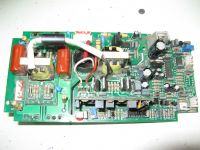
    MGSI-200 IGBT Magnum Welder: No Response to Potentiometer, Need Control Diagram MGSI-200 IGBT Magnum Welder: No Response to Potentiometer, Need Control Diagram

Topic summary

The discussion revolves around the MGSI-200 IGBT Magnum Welder, which is experiencing a lack of response to the potentiometer despite powering on the 15 V supply. Users suggest checking various components, including the CA3140 and TL084 integrated circuits, and the IRFZ24 and IRF9Z24 transistors that may control the IGBT transformer. One user notes that after disconnecting a plug, the output voltage increased significantly, but the current remained low. Another user highlights the importance of the error amplifier circuit receiving a signal from the current transformer, indicating that a damaged transformer could lead to the described issues. Additionally, there are inquiries about obtaining a full schematic diagram for better troubleshooting.
Summary generated by the language model.
ADVERTISEMENT