logo elektroda
logo elektroda
X
logo elektroda

Kraft & Dele KW 6500 Generator: AVR Regulator Damages, 3-Phase Issues, Replacement Options

bzyk69ak47 24234 47
ADVERTISEMENT
Treść została przetłumaczona polish » english Zobacz oryginalną wersję tematu
  • #1 16930798
    bzyk69ak47
    Level 13  
    Hello to all forum members.
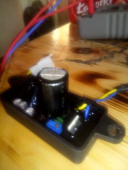
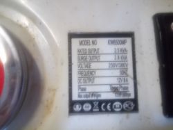
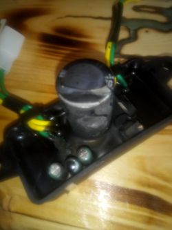
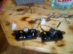
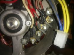
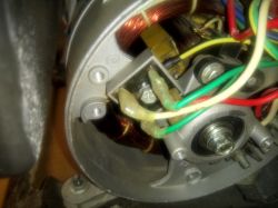
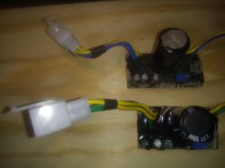
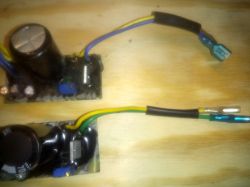
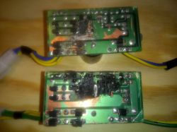
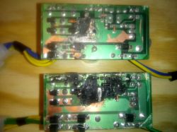
    I have a 3-phase Kraft & Dele KW 6500 generator, Chinese for 700 PLN, of course, since it was new it was neither overloaded nor badly stored (in the rain, etc.), after some time it simply stopped working, I took it apart, actually the generators themselves, it turned out the AVR module is damaged, because when I connect the regulated power supply to the rotor (AVR completely disassembled), at approx. 21 V excitation voltage on all 3 sockets, it gives 230 and 400 for 3-phase nicely. I bought a new module on alledrogo, identical in appearance, only instead of blue wires it had green and the capacitor instead of 220 uF had 470, immediately after connecting and starting the aggregate it literally burned after 15-20 seconds, I complained about it, replaced it with a new one, , but only the ankle, the pins from the excitation hung loose because I wanted to check the polarity and voltage that the AVR gives, I connected the power supply for excitation, and again the same, the AVR is burnt. I picked out the resins from both, both burned plates in the same place, does anyone have any idea why this is happening? I will add that on the ankle, after starting the generator with a power supply, the voltages are 16 V on one pair of pins and 105 V on the other, i.e. 16 is probably. module and 105 is the reference voltage, right? I am adding photos, and can anyone tell which bridge on the avr board should nap. while. and for which nap. comparative? because when I called the Kraft Dele service, some technician from them said that it can be different in Chinese, they could even change the order of the wires in the cube, and the cubes cannot be inserted the other way around. I am asking for help, thank you in advance, best regards. Kraft & Dele KW 6500 Generator: AVR Regulator Damages, 3-Phase Issues, Replacement Options Kraft & Dele KW 6500 Generator: AVR Regulator Damages, 3-Phase Issues, Replacement Options Kraft & Dele KW 6500 Generator: AVR Regulator Damages, 3-Phase Issues, Replacement Options Kraft & Dele KW 6500 Generator: AVR Regulator Damages, 3-Phase Issues, Replacement Options Kraft & Dele KW 6500 Generator: AVR Regulator Damages, 3-Phase Issues, Replacement Options Kraft & Dele KW 6500 Generator: AVR Regulator Damages, 3-Phase Issues, Replacement Options Kraft & Dele KW 6500 Generator: AVR Regulator Damages, 3-Phase Issues, Replacement Options Kraft & Dele KW 6500 Generator: AVR Regulator Damages, 3-Phase Issues, Replacement Options Kraft & Dele KW 6500 Generator: AVR Regulator Damages, 3-Phase Issues, Replacement Options Kraft & Dele KW 6500 Generator: AVR Regulator Damages, 3-Phase Issues, Replacement Options Kraft & Dele KW 6500 Generator: AVR Regulator Damages, 3-Phase Issues, Replacement Options Kraft & Dele KW 6500 Generator: AVR Regulator Damages, 3-Phase Issues, Replacement Options Kraft & Dele KW 6500 Generator: AVR Regulator Damages, 3-Phase Issues, Replacement Options Kraft & Dele KW 6500 Generator: AVR Regulator Damages, 3-Phase Issues, Replacement Options
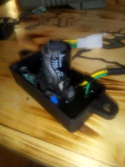
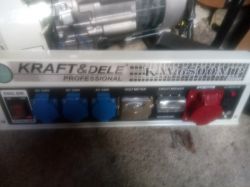
    I will add that in both modules the yellow wires go to the bridge from the S2M diodes (1000V / 3A) and the green (blue) to the M7 diodes (1000V / 1A), the question which should be 105V and 16V, is the module on because of the voltage are replaced or for another reason, but when the generator was new it worked, and now it works without avr only on the power supply ...
  • ADVERTISEMENT
  • #2 17321736
    alladyn-solar-batt
    Level 11  
    I have exactly the same symptoms - after buying a new AVR, this new one lit like a candle. I will fight the topic. Have you measured the rotor and stator resistance?
  • ADVERTISEMENT
  • #3 17322786
    bzyk69ak47
    Level 13  
    Hello, hello :D I was pretty sure the topic had died ...
    Yes, I measured, moreover, two friends have practically the same aggregates, but working, I compared the resistances with others and almost identical, so they are definitely OK ... I checked the brushes, wiring, everything seems OK, that's why it's so strange Everything is fine, but it doesn't work ...

    Added after 9 [minutes]:

    Ps. As for the module, I noticed that from different production they have different polarity at the output, some PLUS is blue (or green) and others are yellow (or brown),
    As I exchanged with a friend in the aggregate, the original one had a plus on the blue, so I connected the new one in the same way, fired and nothing .... it was enough to change the blue with yellow places and it started to kick ... But the reverse polarity connection to the brush holder was not is the reason the module is burning, so the topic is still a mystery ...
  • #4 17322839
    jack63
    Level 43  
    What is the resistance of the ends of the excitation winding to ground?
    What three-phase system does the generator work in? Triangle, star with / without center point derived?
    Could you please draw the regulator power diagram?
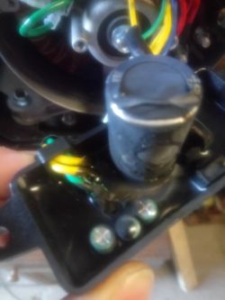
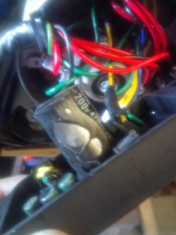
    What voltage is it supplied with, because the capacitor in the photo is only at 200VDC!
  • #5 17323218
    alladyn-solar-batt
    Level 11  
    In my case, we have a single-phase chiller. On the forum they say that the auxiliary stator winding should supply the AVR 105V - so theoretically it seems that with an electrolyte at 200V it should be enough ... Recently I bought a 250V electrolyte. The rotor has 44 ohms (2800W generator), and I wonder which outputs from the stator on the AVR plug are which, because we have two blue and two yellow ones - but which winding from which? On the forum they write that the stator should feed 105V and 16V to the AVR. Should one assume that it is possible to break from the main stator winding (230V) to the auxiliary winding for 16V or the latter for 105V? But how to verify it ...?

    [/ table]

    Added after 7 [minutes]:

    bzyk69ak47 wrote:


    Ps. As for the module, I noticed that from different production they have different polarity at the output, some PLUS is blue (or green) and others are yellow (or brown),
    As I exchanged with a friend in the aggregate, the original one had a plus on the blue, so I connected the new one in the same way, fired and nothing .... it was enough to change the blue with yellow places and it started to kick ... But the reverse polarity connection to the brush holder was not is the reason the module is burning, so the topic is still a mystery ...
    Different polarity at the output is not "dangerous" because, first of all, you can check it with a voltmeter, secondly, on the brush holder at the entrance of the lines to the coats, you have + and - so you can connect the correct polarity despite the "changes" made by quinols. Nevertheless - the mystery of why after connecting the new AVR is still unknown. the new one immediately caught fire in two seconds .... Either there is a breakdown from 230V and the voltage was too high to the AVR, or I don't know ...
  • #6 17323242
    jack63
    Level 43  
    alladyn-solar-batt wrote:
    On the forum they write that the stator should feed 105V and 16V to the AVR.

    What voltage RMS, DC peak. Volts alone are not enough ...
    If the excitation is fed from a separate winding, which would be quite logical, there must be NO electrical connection between this winding and the ground or main winding.
    Unless someone has grounded the center of the star or one end of a single-phase winding.
    Is the field winding shorted to ground by any chance?
  • ADVERTISEMENT
  • #7 17323353
    alladyn-solar-batt
    Level 11  
    I can only assume that it is about 105V RMS ...... It looks like I need to buy a new stator and of course a new AVR, because when I give 25V DC to the rotor from the battery, 240V AC appears on the main stator winding - so the rotor looks operational. Of course, after the purchase, I will measure the resistance of the new stator winding, because I do not know by what miracle, but despite the fact that I was looking for an ikt, I did not measure it, or at least no one on the forum indicated what the resistance of the working stator on individual windings should be.
  • #8 17323518
    gimak
    Level 41  
    alladyn-solar-batt wrote:
    It looks like I need to buy a new stator and of course a new AVR, because when I put 25V DC on the rotor from the battery, 240V AC appears on the main stator winding - so the rotor looks fine.

    In this situation, I would refrain from buying a stator. I do not know what the diagram of this aggregate looks like, but I would advise you to read at least the beginning of this topic https://www.elektroda.pl/rtvforum/topic1824660.html
    I would compare what is here with what is there, I would try to draw some conclusions and only then make a decision.
    I have a similar generator as the one in the link, but I have no 17V tap on the working winding and I would have to think about how to solve this problem.
  • ADVERTISEMENT
  • #9 17323544
    jack63
    Level 43  
    gimak wrote:
    In this situation, I would refrain from buying a stator.

    I also.
    I suspect a mismatch between the regulator and the generator.
    However, you need to check everything carefully.
    Schemes are the basis. They are not complicated. You can also recreate the diagram of a damaged regulator. From the photos you can see that it is quite simple, so maybe it can be repaired and even modified for a given generator.
  • #10 17324400
    Staszek49
    Level 35  
    Buddy, what real voltage is the AVR powered by, maybe too high and that's why it breaks down. In my opinion, the main stator winding is functional. This is evidenced by the generation of voltage around 230 V, after the rotor is powered from a battery. Has the colleague checked the windings for possible short circuits between themselves.

    The aforementioned 17 V voltage applies to the supply of the rectifier system, i.e. for charging the batteries.
  • #11 17324480
    gimak
    Level 41  
    bzyk69ak47 wrote:
    I will add that on the ankle, after starting the generator with a power supply, the voltages are 16 V on one pair of pins and 105 V on the other, i.e. 16 is probably. module and 105 is the reference voltage, right? I am adding photos, and can anyone tell which bridge on the avr board should nap. while. and for which nap. comparative?

    Based on the link I have quoted, it is rather the opposite - a pair of pins with a voltage of 105V is the power supply of the AVR module, and the pins with 16V are the terminals on which the AVR checks the voltage generated by the generator at that moment and compares it with the reference voltage. The result of this comparison is the appropriate voltage (current) supplied to the rotor of the generator.
    Staszek49 wrote:
    The aforementioned 17 V voltage applies to the supply of the rectifier system, i.e. for charging the batteries.

    Perhaps a tap with such a voltage is used for such a purpose, in the quoted link and in this thread it is the control voltage, which the AVR compares with the reference voltage.
    For me, there is no such tap and if I wanted to add AVR to my generator, I would have to use a small transformer that would lower the operating voltage of the generator (230VAC) to 16VAC (in this case).
    I believe that the module used has the wrong parameters, or it is incorrectly connected to the generator.
  • #12 17324569
    bzyk69ak47
    Level 13  
    Hello again, in my case it was a 3-phase generator, star connected with the output from the center of the star, a separate winding output to the rectifier bridge for AKU charging, and the winding output of 16V and about 100V.
    Winding resistance 3phase. between what I remember, there was about 12R (of course, aluminum wire as it is in quinola) and between the neutral one I do not remember, but I know that they were properly symmetrical and none of them showed a short to ground ... while the rotor had some 38R.
    As for the possibility of checking the polarity at the AVR output with a multimeter, I wanted to do so, I disconnected the regulated power supply for excitation, I started the generator (without AVR), I gave such a voltage that the output was nice 230 and 400V, I measured the voltage on the ankle that goes to the AVR, it was nicely almost 16 and 102V, so I decided to plug the cube into the already new 3rd module (without connecting its output to the brushes, to first check the polarity and what voltage it excites) and again, the same as for a friend, 2 maybe 3 seconds and from the module living fire until the resin tore out which was flooded ...
  • #13 17324587
    jack63
    Level 43  
    I see that you are using an "interesting" method to solve your problem ...
    Maybe it's better to throw another AVR into the fire. There will be less work ... Sorry for the sarcasm, but it's starting to get funny, though sad.
    You have to work more with your head and not with your hands ...
    I wrote about creating diagrams and measurements. No response, so ...
    According to me, without a thorough knowledge of the aggregate and regulator, there is no chance of success.
  • #14 17324680
    gimak
    Level 41  
    bzyk69ak47 wrote:
    I will add that in both modules the yellow wires go to the bridge from the S2M diodes (1000V / 3A) and the green (blue) to the M7 diodes (1000V / 1A), the question which should be 105V and 16V, is the module on because of the voltage are replaced or for another reason, but when the generator was new it worked, and now it works without avr only on the power supply ...

    And you do not specify what voltage comes to these colors from the aggregate.
    bzyk69ak47 wrote:
    Yes, I measured, moreover, two friends have practically the same aggregates, but working, I compared the resistances with others and almost identical, so they are definitely OK

    I am surprised that having access to the same or a similar aggregate, you did not check the voltages at the AVR inputs and outputs in this aggregate and compared with those measured at home - once again. And two - if the voltages are similar and on the same pins, I would first check how the new AVR on the aggregate will behave at my friends - whether it will go up in smoke or whether the aggregate will work normally. If it works correctly, you need to carefully check (compare) whether the voltages are the same between the same pins, in the cubes in both aggregates.
  • #15 17325918
    alladyn-solar-batt
    Level 11  
    Well, now (theorizing), the case prompts me to the thesis about the breakdown from the main winding 230V to the winding supplying 105V to the AVR, because it is difficult to explain the "explosive" behavior of the AVR after being powered from the stator by other means. powered from the power supply / worked properly ....
  • #16 17327112
    gimak
    Level 41  
    gimak wrote:
    Well, now (theorizing) the case, however, prompts me to the thesis about a breakdown from the main winding 230V to the winding supplying 105V on the AVR,

    It's by me. also when you theorize, you should track it in the same way by supplying power to the rotor from the power supply. The supply voltage of the AVR when the rotor is powered from the power supply should then be higher and much higher than in the friends' generator.
    Out of curiosity, I will check what is the voltage on the excitation winding (I do not have an AVR).
  • #17 18141562
    GFM
    Level 10  
    bzyk69ak47 wrote:
    Hello again, in my case it was a 3-phase generator, star connected with the output from the center of the star, a separate winding output to the rectifier bridge for AKU charging, and the winding output of 16V and about 100V.
    Winding resistance 3phase. between what I remember, there was about 12R (of course, aluminum wire as it is in quinola) and between the neutral one I do not remember, but I know that they were properly symmetrical and none of them showed a short to ground ... while the rotor had some 38R.
    As for the possibility of checking the polarity at the AVR output with a multimeter, I wanted to do so, I disconnected the regulated power supply for excitation, I started the generator (without AVR), I gave such a voltage that the output was nice 230 and 400V, I measured the voltage on the ankle that goes to the AVR, it was nicely almost 16 and 102V, so I decided to plug the cube into the already new 3rd module (without connecting its output to the brushes, to first check the polarity and what voltage it excites) and again, the same as for a friend, 2 maybe 3 seconds and from the module living fire until the resin tore out which was flooded ...


    It's quite an old topic, but I'm having similar problems and I've figured out something.
    The stator on Chinese models is made of aluminum. The entire stator vibrates in line with the motor. A short circuit between the windings occurs in time with the vibrations.
    When the AVR sees 230 (or similar) instead of 17V, it drastically lowers the excitation. In my case at 3.85 V.
    So at the output I get about 30 V instead of 230. Unfortunately I have to replace the stator and AVR, which I burned while trying to excite external. It is good to buy a stator wound with copper rather than aluminum. Withstands higher currents and is more resistant to vibrations.
    The 6 V battery raised the voltage nicely to 90 V. I thought a step ahead and connected the 12 V 3A power supply. The voltage jumped to 170 V, but not for long. After several seconds, the AVR and the power supply fell.
  • #18 18162540
    boras_ptu
    Level 8  
    I do not know if it will help someone - but I am affected by the same case. The problem is so less that the regulators do not burn :) but what if they are to be replaced anyway (they give excitation over 100V) which results in the output from the generator with a voltage of 450V instead of 230 :( . fear to connect anything because you never know when the regulator will fire.
    When applied from an external 24V source to excitation, the output parameters of the generator are ideal. in addition, the AVR comes out 107V and 18V.
    This 18V comes from the tap on one of the working windings of the generator (107V is an independent winding). My guess is that the AVR is controlled by the tap and reacts to any fluctuations in the generator load - the additional 107V winding is used to power the excitation.
    Since the voltages at the outputs of the windings are OK, the resistances of the working winding are symmetrical, there is no breakdown of any winding to ground, someone has an idea how to choose AVR because I'm tired of buying other modules - theoretically universal - by alleg **
  • #19 18162603
    gimak
    Level 41  
    You're probably wrong to combine it. I have a generator without AVR and I have about 100 V on the auxiliary winding (I do not remember exactly), a capacitor is connected to this winding.
    A conversion of such a generator is described here,
    https://www.elektroda.pl/rtvforum/topic1824660.html
    for one with AVR. In the first post - pay attention to how the AVR was connected there, maybe it will lead you to something.
  • #20 18162648
    boras_ptu
    Level 8  
    When connecting the AVR, you cannot be influenced by the color of the cables - because I already bought 3 and they were different for each one. There are only two wires on the output and one is always marked "+" so a mistake is rather impossible. On the power side there are 4 cables (two of them are always the same color - one yellow, one blue, one brown) and this is the power supply from the additional 100V winding, the other two are the comparative voltage supply from the 16-20V tap (in my case, it is white and black and once yellow and blue and in the original they were white and brown) - the plug is unidirectional so a mistake is excluded.
    The generator worked on the original AVR for about 2 years (several actuations) and if it were not for my attempt to regulate the voltage from less than 220V to 230V it would probably work until today. I turned the potentiometer in the regulator and something clicked - AVR died. The second one worked maybe 2 hours and the light was blinking terribly, so I bought a third one, which after a few minutes burned my halogen lamp with a voltage surge at the output of the generator over 400V (instead of 230).
    I use the generator to power halogens (2x300W) so there is no question of overloading (2kW generator - 3 phases, each lamp for a different socket).
    Before buying the fourth AVR, I measured everything by supplying the excitation with an external source (as I read in the posts, the generator parameters are OK), so I am asking for help, how to recognize the right replacement?

    Added after 6 [minutes]:

    I will just add that the comparative method of selecting a new AVR does not work. everything is covered with black mass and they differ only in the housing (alu or plastic) and the colors of the cables. Sometimes you can see descriptions on this 470uf / 250V large capacitor. nothing more.
    Oh - and the length of the precision potentiometer is different. No plaques or stickers.
  • #21 18162762
    gimak
    Level 41  
    By providing a link to this topic, I did not mean to be influenced by the colors, but how to connect it. I didn't have an AVR in my hands either, so I don't know what it looks like. There is no winding with a voltage of 17 V in my generator, so if I decided to do something like that, I would have to prepare this voltage somehow.
    boras_ptu wrote:
    everything is flooded with black mass

    The ignition module in my generator fell and I couldn't find one anywhere. I assumed that the thyristor had died, but everything was also flooded with black mass. So I prepared the module according to my idea, which surprisingly worked, but the engine sometimes kicked when started. On this forum it was said that it was because of the switched ignition. So I started this damaged module and picked out this black mass and did not even damage anything. I replaced the damaged thyristor and recreated the diagram of this module.
    In this situation, I would start removing this mass from the original AVR and checking what was "cracked" and maybe it would be possible to bring it back to life.
    Initially, I removed this mass with a small drill in a small 12 V drill, but later I got used dental drills from the dentist, and I finished the work with them like a milling cutter.
  • #22 18162792
    boras_ptu
    Level 8  
    Sure - I understand the intentions. I also wrote a little more for posterity.

    Mainly, I mean help in finding the right replacement, because from the outside, they are all in the same housing and they are all universal for 2-4kW generators. Maybe I was just unlucky and got a faulty art. I think I'll do one more approach to the purchase of a "Polish" product (at least that's what they say), at most 5 in the back. I don't do anything with the generator itself, because information from others confirms that it is okay. AVR - this is the cause of my concern.
  • #23 18162808
    gimak
    Level 41  
    boras_ptu wrote:
    The problem is so less that the regulators do not burn :) but what if they are to be replaced anyway (they give excitation over 100V) which results in the output from the generator with a voltage of 450V instead of 230

    And here the question arises, is this 450V voltage available immediately after installing a new AVR, or does it appear only after some time?
  • #24 18163251
    GFM
    Level 10  
    boras_ptu wrote:
    Sure - I understand the intentions. I also wrote a little more for posterity.

    Mainly, I mean help in finding the right replacement, because from the outside, they are all in the same housing and they are all universal for 2-4kW generators. Maybe I was just unlucky and got a faulty art. I think I'll do one more approach to the purchase of a "Polish" product (at least that's what they say), at most 5 in the back. I don't do anything with the generator itself, because information from others confirms that it is okay. AVR - this is the cause of my concern.


    All regulators (with bolt spacing of approx. 100 mm) work exactly the same.
    On the basis of the comparative voltage (approx. 17 V from a tap on one of the phases), they select the appropriate one
    excitation current (taken from the independent winding approx. 105 V). Aggregates with slightly larger ones
    longer cores of stators and rotors have power, and the excitation current is the same. U = dI / dt.
    For aggregates with much higher powers, the AVRs have a screw spacing of approx. 140 mm.
    If the stator is OK, the "wrong" AVR may give a voltage other than the nominal 220/230.
    It is a good idea to measure the voltage on the LOAD phase using an extension cord with a power strip.
    As a rule, the voltage is much higher without load. This equipment is not designed to be powered
    electronics. It's rather for drills, grinders, etc.
    If the voltage is ridiculously low, then undoubtedly a breakdown occurs due to vibrations
    and the AVR sees something much higher instead of 17V and lowers the excitation accordingly. I have come to this
    after burning the first AVR. I bought the aggregate damaged for ridiculous money.
    I personally bought a new (supposedly) Polish copper-wound stator (checked) on Alleg **
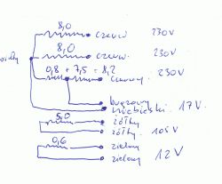
    for 240 zeta + mail. I enclose his diagram with resistances, colors of the cables at the outputs and voltages.

    Kraft & Dele KW 6500 Generator: AVR Regulator Damages, 3-Phase Issues, Replacement Options

    It is good to measure the stator and determine the phase from which the 17 V tap comes; then toggle this
    the phase to the first outlet from the voltmeter, the voltmeter to it, and load them first / average power.
    The voltmeter (if properly calibrated) will show the actual value under load.

    One more word about how to know what the power of the aggregate is. First, redundant, second
    length of the stator iron core. Mine is 70 mm, the excess (3f) C3 which means about 2 kW.
    And the nameplate shows 7.1 kW at 3F and 4.2 kW at 1F. The Chinese are darkening the power.
    On Alleg ** you can see what other stators are available. https://www.elektroda.pl/rtvforum/posting.php?mode=quote&p=18162792#
  • #25 18164526
    smerdendes
    Level 12  
    Hello. Sorry that I will connect to the topic, but it seems to me that it makes no sense to set up a new one ... I have a similar, Chinese aggregate only called HONDA and the problem is that after firing there is no voltage, it appears for a moment to the rotor brushes I will give 12V and then it is all the time. If you turn it off and start after 5-10 minutes, it wakes up normally and everything is OK, but if it stands for 1-2 hours, you have to wake it up again to give voltage ... All resistances are fine and voltage during operation also ....
    Maybe someone knows how it arouses, are there any magnets in the rotor or stator? e.t.c?...
  • #26 18164919
    gimak
    Level 41  
    smerdendes wrote:
    Maybe someone knows how it arouses, are there any magnets in the rotor or stator? e.t.c?...

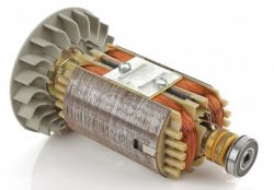
    Evidently he has a weak residual magnetism. In my case, there is one neodymium magnet stuck to the rotor. On the other side of the rotor there is room for the other one, I don't know if they forgot to add it or it flew out. The aggregate on this one magnet excites without any problems.
  • #27 18165050
    smerdendes
    Level 12  
    Thanks for the answer, you will probably not take pictures of me anymore because it is known that you will not start the generator :) but if you remember +/- where this magnet is, please mark it on the attached photo ... and one more thing, if I remove this screw from the back of the rotor, then I can remove it without any problems? of course, after disassembling the stator ...
    Kraft & Dele KW 6500 Generator: AVR Regulator Damages, 3-Phase Issues, Replacement Options
  • #28 18165190
    gimak
    Level 41  
    You can see the photos, because they are posted here https://www.elektroda.pl/rtvforum/topic3450586.html#17154946
    The third photo shows a rotor with a milled magnet key. There is no magnet here, but it's on the opposite side.
    In the attached photo the magnet is visible in the pole groove on the bearing side.
    Quote:
    and one more thing, if I remove this screw from the back of the rotor, then I will be able to remove it without any problems? of course, after disassembling the stator ...

    I don't know your generator, but if the rotor looks like the picture, then yes. Probably from the side of the fan, it will be seated on the cone of the motor shaft and will not want to get off it and will have to be helped.
    For me it is the opposite, to remove the stator I have to remove the rotor first.
  • #29 18165541
    boras_ptu
    Level 8  
    Smerdendes - do not follow your friend's suggestion because you have a completely different generator design. A colleague has a self-excited generator without AVR, and here I would look for the cause.
    Residual magnetism does not disappear by itself. generators that have been in stores for several years would never start :) First wipe the commutator, check the brushes and start testing the AVR module. Measure symmetry, resistance of windings and check that nothing is coming to ground. If our ALU windings (99% of cheap aggregates on the market) often the reason is the connection of the winding with the wire coming from the stator.
  • #30 18165567
    GFM
    Level 10  
    It can be different with the disappearance of residual magnetism - it all depends on the material (type of steel),
    from which the rotor is made. I had the engine spinning and there was no electricity - zero voltage.
    But it was enough to nudge the battery with the voltage on the brush-holder and the voltage appeared - some weakness
    something like 190 V. The same when trying again. No voltage, and after tapping the battery, the same 190.
    Then I connected the load - a 1000 W heat gun - it worked, but somehow poorly (190V).
    Then I shifted to second gear (1500W), the engine grunted and the voltage jumped to something like 300V.
    After another firing, the tension was high. Now I have to go down to around 230.

Topic summary

The discussion revolves around issues with the Kraft & Dele KW 6500 generator, specifically focusing on the failure of the AVR (Automatic Voltage Regulator) module and its compatibility with the generator's 3-phase system. Users report that after replacing the damaged AVR, the new units often burn out or fail to regulate voltage correctly, leading to dangerously high output voltages. Various users share their experiences with measuring rotor and stator resistances, checking for short circuits, and verifying the correct polarity of connections. Some suggest that the problem may stem from mismatched components or faulty wiring, while others recommend purchasing higher-quality AVR replacements. The conversation highlights the importance of understanding the generator's wiring and voltage specifications to avoid damaging components.
Summary generated by the language model.
ADVERTISEMENT