logo elektroda
logo elektroda
X
logo elektroda

FAAC 740 Sliding Gate Actuator - Radio Connection, Pilot Coding, Terminal Guide (COM, NC, NO)

piomar93 27720 14
ADVERTISEMENT
Treść została przetłumaczona polish » english Zobacz oryginalną wersję tematu
  • #1 16824575
    piomar93
    Level 5  
    Hello, gentlemen, automation engineers!

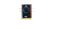
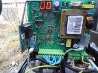
    Well, I have an actuator for the sliding gate FAAC 740. I have already connected everything but I stopped on one thing: how to connect the radio to the entire drive system. The terminals have the following terminals: COM, NC, NO. I think I should connect the negative pole (-) to the COM and the end of the NO contact to the OPEN A terminal (total opening). I will add that I made a local switch via the bell switch (the one with the spring) and this option works correctly. The second problem is coding the control panel and coding the pilots to FAAC.
    I add pictures of the radio and pilots:
    FAAC 740 Sliding Gate Actuator - Radio Connection, Pilot Coding, Terminal Guide (COM, NC, NO) FAAC 740 Sliding Gate Actuator - Radio Connection, Pilot Coding, Terminal Guide (COM, NC, NO)
    I am asking for a hint.
  • ADVERTISEMENT
  • #2 16824862
    zybex
    Helpful for users
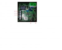
    Place the receiver in the connector and do not connect anything. It must work. The connector in question has a green sticky note attached.
    This is to look like in the picture below (found on the net).

    FAAC 740 Sliding Gate Actuator - Radio Connection, Pilot Coding, Terminal Guide (COM, NC, NO)

    One channel of this receiver is just output there (except for power supply). At this point, you should already control the remote in the same way as the button connected directly to the drive. I do not know if they are already trained in the receiver when they buy the remote controls. If not, then there must be some instruction to teach them.

    If you deal with this and the drive will work properly (set limit switches and possibly photocells), then you will be able to use the second channel that this receiver has. It can be controlled by something extra, eg garage door or wicket function, or lighting). Then you use the contacts shown in the first picture (COM, NC, NO).
    Is everything now fairly clear?
  • ADVERTISEMENT
  • #3 16825902
    piomar93
    Level 5  
    I understand, but write me exactly how to code the control panel and remotes. And what are the two buttons for the two channels for?
  • ADVERTISEMENT
  • ADVERTISEMENT
  • #5 16826055
    kotbury
    Gantry automation specialist
    PS. I would like to add that channel 1 is received by the central unit through a pin connector and is used for normal gate commissioning (ie step by step) and channel 2 does not support the second channel through the connector - you can connect the COM and NO terminals of the receiver to 7 and 2 of the control panel by connecting them to the function partial opening (wicket) or using peripherals for other purposes (eg to operate an electronic bistable relay and through it to turn the lighting on and off).
  • #6 16829277
    piomar93
    Level 5  
    Gentlemen, I set everything as it should, according to the instructions and everything works correctly. Also, I can confidently close the topic.
  • #7 19010271
    chinczyk3000
    Level 11  
    Hello,

    He will heat up the old cutlet so as not to create a new topic. How to connect another receiver to this Faac 740 drive? e.g. Proxima NW1. I want a gate and garages on one remote. There are 5 pins on the drive board. The radio has a power supply, an antenna and a contactor. Someone something ?
  • #8 19010305
    xury
    Automation specialist
    Why do you want to connect Proxima to the pins from the radio?
    You have everything you need on the connectors. 24V power supply and openA and openB opening
  • #9 19010987
    chinczyk3000
    Level 11  
    I thought that when I get rid of the original radio, the replacement must be connected to the same pins, but OK, I already know that it is not. How is openA different from openB? understand ground control.
  • #10 19010996
    xury
    Automation specialist
    Open A is complete opening. Open B is a partial set aside, the so-called wicket.
    Of course, as in 90% of modern electronics, mass control.
    By the way, the radio pins are the same signals as on the connectors.
  • #11 19015775
    chinczyk3000
    Level 11  
    Thank you for your answer :) Everything works as I wanted :)
  • #12 19379474
    chinczyk3000
    Level 11  
    Another question for this drive - is there a signal on the connectors or somewhere that can be pulled out to know if the gate is closing, is it closed or open?
  • #13 19379845
    zybex
    Helpful for users
    On the disc (post 2) you can see 8 LEDs that turn on and off when the drive is running. This is some information for the installer, service technician. Unfortunately, this information is not pulled onto the connector.
    The only information I get out is that the gate is moving (no matter which way). This is powering the beacon.
  • #14 19380643
    xury
    Automation specialist
    On the new boards, it is possible to extract information about the open or closed gate from the connector of the control panel. It is not described in all versions of the manual.
  • #15 19380773
    kotbury
    Gantry automation specialist
    Maybe not so much new, but with a richer version of the firmware (I just met one with older copies). You can recognize the presence of the rP function in the menu (release before the limit switch), and the WL lamp also has an electromagnetic lock mode - and better signaling of the gate status (it blinks when it is moving, it lights up when it is open and stopped, it goes out when it is closed).
    If you have a drive with a "trimmed" firmware (WL repeats the rooster in the signaling mode), you can always connect the Proxima AKZ device between the switch and the drive board. It is a "transparent" repeater of the limit switch state on separate contacts for the drive.
    If you are a haunted DIY, you can put a phototransistor with signaling circuit on the FCA LED (it will work in the dark with the box closed ...)

Topic summary

The discussion revolves around connecting a radio receiver to the FAAC 740 sliding gate actuator. The user seeks guidance on wiring the radio to the actuator's terminals (COM, NC, NO) and coding the control panel and remotes. Responses clarify that the receiver should be connected to the appropriate terminals, with COM linked to the negative pole and NO to the OPEN A terminal. Instructions for coding the remotes are provided via a link to a programming manual. Additional queries about connecting a different receiver (Proxima NW1) and understanding the functions of the Open A and Open B terminals are addressed, with explanations on their respective uses for complete and partial gate openings. The conversation concludes with successful implementation of the setup.
Summary generated by the language model.
ADVERTISEMENT