logo elektroda
logo elektroda
X
logo elektroda

Children's Car Repair: Control Board Damage, Door Switch, D2+/D2- & D1+/D1- Wires, Replacing Remote

wentyl215 11952 13
ADVERTISEMENT
Treść została przetłumaczona polish » english Zobacz oryginalną wersję tematu
  • #1 16834539
    wentyl215
    Level 19  
    Hello, I would like to try to repair a children's car and I have a few questions.

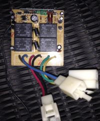
    In general, I suspect damage to the control board (photo below) or the switch in the door. The drive (motor) is operational, the battery needs to be replaced, but before replacing it, I want to run it from a different power supply.

    I do not know what the D2 + / D2- and D1 + / D1- wires are for, in the middle is +/- so probably the power supply of the board that is connected to the switch in the door, also the power connection to it should indicate some voltage on the board, only where and what?

    Another thing is the pilot ... the previous owners threw the remote control (if the car broke, it was unnecessary), is there any possibility to buy a remote control? Do you need to solder something on the PCB?
    Children's Car Repair: Control Board Damage, Door Switch, D2+/D2- & D1+/D1- Wires, Replacing Remote

    Children's Car Repair: Control Board Damage, Door Switch, D2+/D2- & D1+/D1- Wires, Replacing Remote

    Children's Car Repair: Control Board Damage, Door Switch, D2+/D2- & D1+/D1- Wires, Replacing Remote
  • ADVERTISEMENT
  • #2 16834641
    1 PAWEL
    Level 42  
    Please enter some name, symbol, photo of the car.
  • ADVERTISEMENT
  • #4 16835036
    michalek1988
    Level 26  
    Maybe D1 and D2 go to the motors, you can connect the power supply to the middle connector without any problems, remember about the correct polarity and value. I suppose the relays control driving forward, backward, turns, so if any of these functions did not work for you, it would be worth taking an interest in them. What do you build your suspicion about a damaged control board? We cannot rule out that the entire toy was redundant due to battery wear. If you can, take a picture from the side of the tracks and include it in the first post.
  • #5 16836549
    wentyl215
    Level 19  
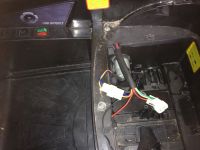
    The first post was changed, photos of the board on both sides, and a photo of the car.

    There are several buttons in the door, the most important are POWER and control change, i.e. manual, where the gas pedal, reverse and steering wheel are working, and remote control.
  • ADVERTISEMENT
  • #6 16836588
    michalek1988
    Level 26  
    Do you have an original battery? you will be given the operating voltage on it. Red and black probably connects to it, check with an ohmmeter if you have a switch on this switch. If you are ok, if not, then you have to take the door apart and check why it doesn't work. There is only one engine? I would rather suspect there are 2 left and right wheels separately. Switch to manual, and without motor, check that the relays switch when you accelerate, brake, test a turn. PS did you get this board removed or was it connected in some way?
  • #7 16836745
    wentyl215
    Level 19  
    The pass of the plus (power switch) works, but I assume that I will not miss the demolition of the door, because the manual switch is suspicious. One motor per wheel :D

    The board sat next to the battery and drive (3rd photo). On the battery we have a stb 6.75V-6.90V, cycle use 7.20-7.50V with Initial current less 1.75A.
  • #8 16836773
    michalek1988
    Level 26  
    D1 and D2 may be designations for the manual / pilot control module. Different colors of wires come out of the motors than on this PCB. So disassemble the door and see how things are going there, you can take pictures to make it easier for you to put it back together. It turns out that the battery has a nominal 7.2V.
  • #9 16836803
    wentyl215
    Level 19  
    Okay, we already have something ... the manual switch did not touch, briefly at 6V, consumption 0.2A, and when pressing the gas pedal for a moment 1.7A and then constant 1.2A - the wheel turns quite weak, of course the amperage increases with increasing voltage and automatically the drive accelerates.

    So now the question is, to what voltage can I connect this toy to the maximum? There is 12V on the switches / relays, unfortunately not the maximum voltage on the drive.
  • #10 16837211
    michalek1988
    Level 26  
    I already answered you, in the previous post, you have work voltage and work voltage there. The starting current is high, because you have to move the whole mass of the vehicle, overcome the inertia. In an "adult" car, you also need to add more throttle to make it move, and when you accelerate, you can let it go completely and the car will keep moving. Check out the rest of the features we talked about.
  • #11 16837223
    wojtek 9007
    Level 40  
    Hello - there is a symbol on the side of the printed circuit board (PCB) on its base
    determine what voltage was supplied to the car.

    Added after 41 [seconds]:

    Children's Car Repair: Control Board Damage, Door Switch, D2+/D2- & D1+/D1- Wires, Replacing Remote
  • ADVERTISEMENT
  • #12 16837925
    wentyl215
    Level 19  
    I have the T9K-R1, in a black housing, but there is nothing on the plastic. The car is powered by 6V because it is the original battery, but I am wondering about the battery, e.g. 9V or even 12V. The car normally has a cut for the second motor / drive, also with higher voltage, maybe the plate will last because as I wrote earlier ... the relays are 12V, I just don't know if the motor will fail ...

    @ michalek1988 there is nothing to look at there, the fault has been detected and it works. Now I have a dilemma with the battery, if I can with more voltage, I will take one. And also the question of the pilot himself. On the part of spare parts, it comes out that it is enough to buy a remote control for PLN 38 and it should work, right?
  • #13 16837985
    wojtek 9007
    Level 40  
    Currently, for 6V power supply, the diagram probably looks like this;

    Added after 1 [minutes]:

    Children's Car Repair: Control Board Damage, Door Switch, D2+/D2- & D1+/D1- Wires, Replacing Remote

    Added after 1 [minutes]:

    And this is the scheme for 12V;
    Children's Car Repair: Control Board Damage, Door Switch, D2+/D2- & D1+/D1- Wires, Replacing Remote
  • #14 16838158
    wentyl215
    Level 19  
    It will be useful ... I don't know what yet, but I'll come up with something and let you know about the results.

    There is still this pilot.

    btw. I misread the relay, so as not to confuse anyone, it has a value of 12A ...

Topic summary

The discussion revolves around troubleshooting and repairing a children's car, focusing on potential control board damage and door switch issues. The user suspects the control board may be faulty and seeks clarification on the function of D1+/D1- and D2+/D2- wires, which are believed to connect to the motors. The user also inquires about replacing a lost remote control and whether soldering is required on the PCB. Responses suggest checking the battery voltage, testing the door switch, and examining the relays for proper function. The user confirms the car operates on a nominal 6V battery and considers using a higher voltage, while also confirming the relays are rated for 12V. A remote control can be purchased for approximately PLN 38, which should be compatible with the car.
Summary generated by the language model.
ADVERTISEMENT