logo elektroda
logo elektroda
X
logo elektroda

Voltage Issue on Socket Pin: Legrand 40A 30mA Differential, 3-Wire x2.5 Cables, 3x1.5 Switches

ferguson6600 40407 46
ADVERTISEMENT
Treść została przetłumaczona polish » english Zobacz oryginalną wersję tematu
  • #1 16861765
    ferguson6600
    Level 21  
    Gentlemen, I have a small problem with the voltage on the socket pin. I can describe the installations, there is power in the house, 3 fuses on the phases for individual rooms on the board, the Legrand 40A 30mA differential in front of them. I did the installation around the house myself, 3-wire x2.5 cables for sockets, for 3x1.5 switches for 2x1 line halogen lights. If I want to connect the PE wire, it turns off the differential, I decided to check today what is wrong. On the board, I did not connect the PE wire on any phase during the tests, and yet the pin is lit. The tester is lit on the grounding pins, despite disconnected devices and disconnected contacts. The meter shows a result of 4V to 5V, I called all the sockets at the angle that maybe I shorted PE with N somewhere because I have 2 sockets without grounding, everything is well connected, N from N, PE from PE and L from L. I have it on 2 phases and the result identical 4V to 5V. Can this behavior happen if I did not put L on the led switch, but N, and the phase went directly to the leds? Maybe some suggestion what else I can check, and maybe check one phase, and disconnect the other 2 for the time of testing?
  • ADVERTISEMENT
  • Helpful post
    #2 16861796
    elpapiotr
    Electrician specialist
    Alee. You want to have a good call from an electrician, and not to rummage in the installation yourself.
  • Helpful post
    #3 16861822
    zster

    Level 28  
    elpapiotr wrote:
    You want to have a good call from an electrician, and not to rummage in the installation yourself.


    I support 100%.

    Only two things can be added:
    1. A simple tester or a high-impedance voltmeter are not reliable tools for such diagnostics.
    2. How is the PE installation in the distribution box made? Do you split PEN into PE and N in it? And where exactly do you want to connect this PE that triggers the differential?
  • #4 16861824
    ferguson6600
    Level 21  
    Thanks for the info, but I don't have 2 left hands to repair. But it's overwhelmed me and I don't know what's going on, because the devices are disconnected and the pin is on.

    Of course, I have PE and N strips in the box, and they are well plugged in. I want to connect the grounding of the installation to the PE strip for now from one phase, in terms of the installation of the kitchen, bathroom and corridor. If I hook up, the difference is thrown out.
  • #5 16861832
    Krzysztof Kamienski
    Level 43  
    ferguson6600 wrote:
    On the board, I did not connect the PE wire on any phase during the tests, and yet the pin is lit
    Which bolt is on? And what color? :D Do you, laymen, rummaging like chickens, willfully in the installation, have to provoke us, hmm, professionals to ironic answers? After your description you can see total secularism and lack of knowledge in the subject. As they always say on the Forum - Kumaty Electrician Necessary!
  • Helpful post
    #6 16861833
    kozi966
    Moderator of Electricians group
    ferguson6600 wrote:
    on 3x1.5 switches

    Mistake number 1.
    ferguson6600 wrote:
    for halogen 2x1 strand

    Mistake number 2.
    ferguson6600 wrote:
    On the board, I did not connect the PE wire on any phase during the tests, and yet the pin is lit.

    I do not understand this statement. What does PE have to phases?
    ferguson6600 wrote:
    The tester is lit on the grounding pins, despite disconnected devices and contacts

    The tester is not a measurement, it is once, two PE are connected or not? (but not for "pins", but for "power").
    ferguson6600 wrote:
    because I have 2 sockets without grounding

    Mistake number 3.
    ferguson6600 wrote:
    Can this behavior happen if I did not put only zero phase on the led switch,

    There is no right to be zero in a new installation.
    ferguson6600 wrote:
    Maybe some suggestion what else I can check, and maybe check one phase and disconnect the other 2 for the duration of the tests?

    Check the continuity of the protective conductors, fault loop impedance, correctness of connections.
  • #7 16861843
    elpapiotr
    Electrician specialist
    And does a colleague have at least a meter that will surely find voltage on these protective pins?
    Just because the neon voltage indicator is lit does not mean that there is min. Voltage.

    Besides, the installation has a lot of errors (for example sockets without protective pins), what should be surprising?
  • #8 16861875
    kSmuk
    Level 21  
    ferguson6600 wrote:
    3 fuses on phases for individual rooms on the board,

    This is probably a joke.

    ferguson6600 wrote:
    I did the installation around the house myself,

    This is the cause.

    I will not comment on the rest of the mistakes, my colleagues have already done it.
    The installation from the description probably does not even meet the minimum safety requirements or standards.

    Take photos of the trimmed switchgear with the connections well visible. However, the repair or replacement of the installation should be done by an electrician!
  • #9 16861903
    ferguson6600
    Level 21  
    I do not understand what a joke? In the installation in the board behind the differential, I have 3 fuses on individual phases to which individual circuits in the house are connected. Gentlemen, why not give wires, for example 2x1 braided line for LED halogen lights, if they still take a voltage of 5 W? And of course I will take a photo of the board and paste it, but tomorrow, because today is already late.
  • ADVERTISEMENT
  • #10 16861916
    kozi966
    Moderator of Electricians group
    ferguson6600 wrote:
    Gentlemen, why can't you give wires, e.g. 2x1 braided line for LED halogen lights, if they still take a voltage of 5 W.

    You cannot, because this is what Polish law and related standards provide. The circuits are to have separate protective and neutral conductors, and each circuit should have a protective conductor connected.

    Moreover, if there are only these three protections on everything (receivers), the installation is incorrect.
  • #11 16861918
    elpapiotr
    Electrician specialist
    ferguson6600 wrote:
    I do not understand what a joke, in the installation in the board behind the differential, I have 3 fuses on individual phases to which individual circuits in the house are connected. Gentlemen, why can't you give wires, for example 2x1 braided line for LED halogen lights, if they take a voltage of 5W anyway. And I will take a photo of the board, of course, and paste it tomorrow, because today is already late.

    Well, because it is against the regulations. (We are talking about installation> 230 V, of course).
    What regulations? - as an electrician a colleague should know.
    I will give you a hint that it is about the Construction Law Implementing Regulation.
  • ADVERTISEMENT
  • #12 16861940
    ferguson6600
    Level 21  
    Well, I will not correct it now, there is no such possibility. But it is probably not the cause of this that the differential turns off. I am just bothering about where the minimum voltage of 4V appeared on the ground pin (measured with a meter) if, as I wrote, I have not yet connected the PE wire to the PE strip in the board, and I have properly connected in the sockets according to the standards, and the devices are disconnected from them.
    And gentlemen, I am not an electrician by profession, but as I wrote, I do not have 2 left hands. Well, there is a mistake somewhere.
  • #13 16861957
    elpapiotr
    Electrician specialist
    The error is in ... the meter and the measurer.
    Take another, analog one, re-measure the voltage.
    There will be surprise.

    PS. Why does a non-electrician do a job they are unfamiliar with?
  • Helpful post
    #14 16861966
    kozi966
    Moderator of Electricians group
    ferguson6600 wrote:
    so far, I have not connected the PE wire to the PE strip in the board

    And you're surprised there's some tension on that ... pin. The worst thing you could do.

    The principle bows: First we protect, then we power up.

    Ever heard a colleague (in physics) about inductance and capacitance?
    By the way, topic to read:
    https://www.elektroda.pl/rtvforum/topic3263074.html
  • #15 16861971
    zster

    Level 28  
    ferguson6600 wrote:
    so far I have not connected the PE wire to the PE strip in the board


    This is the reason ... Therefore, you can put simple, neon testers or high-impedance meters ... in the box, let them sit ;) Tension is not everything. In this case, what matters is the intensity ...
    When it comes to triggering the "differential", I sense a connection error.
  • #16 16861977
    ferguson6600
    Level 21  
    Well, I just have one for electronics and this tester, why are you writing with surprise it will not show anything? I am 100% sure that it is good to connect, well, maybe apart from grounding to lamps with no and cross-section of wires to these halogens. Tomorrow I will do so that I connect the PE wires individually to the PE strip in the board (I mean individual circuits) and see where the differential will turn off. This will narrow down the search for which circuit turns off the differential. I will connect individual circuits without receivers for now, if I do not turn off the differential, I will connect the receivers one by one. This is how I will do all 3 circuits in sequence and let you know tomorrow.
  • #17 16861983
    kozi966
    Moderator of Electricians group
    ferguson6600 wrote:
    I am 100% sure that it will be connected well

    If 100% sure it's okay, why turn it off?
  • Helpful post
    #18 16861984
    LemuRR 11
    Level 26  
    I am also not an electrician by profession, but an electronics engineer. Why is this happening? I will consider from an electronics point of view ... you have 3 wires, NL PE, quite close together. You know how a capacitor works, probably for AC voltage it is impedance. If PE hangs in the air, a capacitive log is formed between N PE L, and PE if it hangs in the air, it is no wonder that you have some potential on it. Reduce the input impedance of the meter (for example with a resistor) to about 5kR and the problem will go away.
    As for the release of the security:
    First, I would check the correct connection of the RDC.

    EDIT
    I shot the stupidity instinctively with this impedance reduction .. This is what you do with low voltages.
    In this case, you need to use appropriate measuring equipment.
  • #19 16861992
    ferguson6600
    Level 21  
    One more thing, should I change the wires in the switches, in the sense that the N wire is directly to the lamps and halogens, and the L wire through the switch, or leave it like that.
  • #20 16861998
    LemuRR 11
    Level 26  
    ferguson6600 wrote:
    One more thing, should I change the wires in the switches

    Necessarily
  • #21 16862100
    Brivido

    Level 34  
    ferguson6600 wrote:
    One more thing, should I change the wires in the switches, in the sense that the N wire is directly to the lamps and halogens, and the L wire through the switch, or leave it like that.

    And what was the reason for such execution?
  • #22 16862773
    kSmuk
    Level 21  
    ferguson6600 wrote:
    One more thing, should I change the wires in the switches, in the sense that the N wire is directly to the lamps and halogens, and the L wire through the switch, or leave it like that.

    Once the entire installation is done, it's no wonder nothing works.
    Does the colleague know what the network layout is there, or did he do it "as long as it shines"?

    From reading the posts, one can only conclude that the installation is probably amenable to immediate disconnection and for improvement by an ELECTRICIAN!

    Take a picture of this switchboard! It seems to me that the reason is simpler than it might seem.
  • #23 16862944
    CYRUS2
    Level 43  
    LemuRR 11 wrote:
    Reduce the input impedance of the meter (for example with a resistor) to about 5kR [/ u] and the problem will disappear.
    10W of power on the resistor.
    LemuRR 11 wrote:
    I shot the stupidity instinctively with this impedance reduction .. This is what you do with low voltages.
    You didn't shoot the stupid thing.
    You need to calculate to what level to lower the resistance.
    For this in electricity there is a test tube, 7W - 15W
  • ADVERTISEMENT
  • #24 16863483
    ferguson6600
    Level 21  
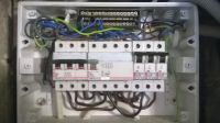
    Gentlemen, I must show remorse because I made a culpable mistake. I connected the brown wires to the N strip, although I do not know how it happened, the brown wires, i.e. L, and at the output of the N fuses, I only noticed it today, although I looked at the boards several times. After replacing the wires, I connected the circuits one at a time, and the full ground is already working on 2, the ground is no longer lit. However, it also turns off the differential on the last circuit, the sockets and switches are checked in the rooms and are well connected, but I have a bad connection somewhere in the woodshed because it turns off the differential. The installation was not changed there, but I will fix it on Monday. On the other hand, I connected all the switches correctly, and the L wire goes through them, the fact that there was no voltage on them is the effect of changing the wires in the board. At the bottom is a photo of my board after replacing the wires.

    Voltage Issue on Socket Pin: Legrand 40A 30mA Differential, 3-Wire x2.5 Cables, 3x1.5 Switches .
  • #25 16864164
    bahus
    Level 12  
    Hello.
    The installation in the woodshed is unchanged, but I hope it is a 3-wire one, because, in the case of a 2-wire one, it cannot be connected via an RCD.

    PS. This "separation" leaves a lot to be desired in technical terms.

    Unfortunately, you cannot see the connected N terminal on the bottom of the RCD, so there are also caveats here.
  • #26 16864180
    lukaszd82
    Level 31  
    People die because of such mistakes ... Massacre ... The covering of this switchboard is also terrible ...
  • #27 16864243
    Krzysztof Kamienski
    Level 43  
    bahus wrote:
    Unfortunately, you cannot see the connected N terminal on the bottom of the RCD,
    Exactly. So why is this RCD there? To make it look nice, of course after putting on the "lid" :D
  • #28 16864433
    wada

    VIP Meritorious for electroda.pl
    Krzysztof Kamienski wrote:
    bahus wrote:
    Unfortunately, you cannot see the connected N terminal on the bottom of the RCD,
    Exactly. So why is this RCD there? To make it look nice, of course after putting on the "lid" :D

    Made to measure - a specialist
    And something very thin is wine - cables as for the 20A fuses
    And even the RCD protected the life of this plug in this case
    Voltage Issue on Socket Pin: Legrand 40A 30mA Differential, 3-Wire x2.5 Cables, 3x1.5 Switches
    I think this photo fits this topic very well
    Photos of the best and worst electrical installations.
  • #29 16864849
    kSmuk
    Level 21  
    B20 for 1.5 mm?. Massacre!
    Get an electrician before you burn yourself down or burn someone down in this house!
  • #30 16864850
    stacho60
    Level 15  
    Hello
    Switchgear for immediate disconnection, among other things because all the neutral conductors N connected in front of the RCD and giving other advice in this case will only be harmful.

Topic summary

The discussion revolves around a voltage issue on a socket pin connected to a Legrand 40A 30mA differential circuit breaker. The user describes their home electrical installation, which includes 3-wire x2.5 cables for sockets and 3x1.5 cables for switches. They report that connecting the PE wire causes the differential to trip, and they observe a voltage of 4V to 5V on the grounding pins despite having disconnected devices. Various responses suggest that the user may have made wiring errors, particularly with the connection of L and N wires, and emphasize the importance of proper grounding and circuit protection. Several participants recommend consulting a qualified electrician to rectify the installation, which appears to have multiple safety violations and incorrect configurations. The user acknowledges mistakes in their wiring and plans to correct them while seeking further advice on proper electrical practices.
Summary generated by the language model.
ADVERTISEMENT