Hello
I decided to explore the knowledge of stepper motor control. How it is built, what its types and applications are known to me, but only the implementation of one of the projects I set up contributed to the deepening of knowledge, especially in the field of its operation with the AVR microcontroller.
To start the project, I purchased a stepper motor model: JK86HS78-4802-04 with a torque of 4.6Nm; more detailed information is provided below:
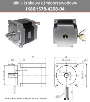
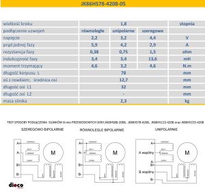
as it is an 8-wire motor, I present how to connect it; for JK86HS78-4802-05 and JK86HS78-4802-04 it is the same, and the only difference between these models is the axle width where for -05 we have 12.7mm, while in -04 as seen above is 14mm
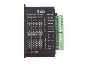
Due to the driver used, it is the TB6600 driver with max current per phase 4A which looks as follows
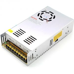
I used a bipolar serial connection, but to power it I used a 24V power supply with S-360-24 nominal and 15A capacity;
Theoretically, I would like to remain with this tension for technical reasons of other elements of the project. For example, the control lamps or 24v fans used, which are more easily available and cheaper than models with a nominal 48v voltage. Apart from the very fact of the driver's limitations, where the maximum possible voltage is 42V, which significantly excludes the use of a 48v power supply, although you could use a 36V power supply and 48v fans which usually work from 24 to 52v but only if we would like to improve the performance of the stepper motor, i.e. obtain more torque at higher revs, which translates into an increase in maximum revolutions.
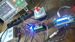
Moving on to testing, I built a simple controller:
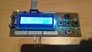
on board with an ATMEGA 8 processor; 16MHz outdoor quartz; 2x16 display, 5-button keyboard, programming interface, LM2596 step-down converter; additional connectors that I will not discuss because they are not the subject of the issue, but the avr program.
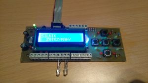
The controller is designed to display the current direction of rotation and the current speed at which the motor axis is spinning.
You can change them via the keyboard: right / left direction; speed from 1 to 100%.
When choosing the maximum value, the motor does not significantly lose the holding torque, as this parameter plays a key role in the design.
I would like to choose the engine speed so that I can use its resources to the maximum. Alternatively, during work, calibrate them and save them to the memory of the system, but this is already on "finito"
In addition, it considers the possibilities of slow starting and braking.
Assuming the initial assumptions, I started to check if there is a ready solution on the web, but I did not find an exhaustive statement, but the project closest to my topic is:
http://mikrokontrolery.blogspot.de/2011/03/Si...kowy-sterowany-mikrokontrolerem-ATmega16.html
And in the same way, I decided to check it, modifying it more for myself, which resulted in the engine being able to start and the axis rotation direction to be changed without any problems
Left arrow, the auxiliary diode is off which translates into a low state on the DIR input of the driver.
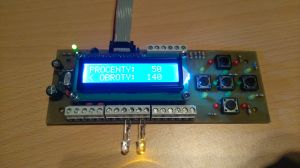
Right arrow, the auxiliary diode is on which translates into a high state on the DIR input of the driver.
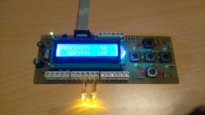
The PUL input, to which the clock waveform is fed, is used for speed control.
And this is the biggest problem, because the motor turns slowly, jerking because the given frequency from the above design is incorrect for it.
And hence the question arises what range should be in order to properly control this engine from the lowest to the maximum revolutions: /
How to determine the maximum speed if I do not have the engine operating characteristics on which we have the "TORQUE / SPEED" graph given as Nm / Hz or Nm / RPM. I would like to add that I do not have a function generator yet to thoroughly examine the frequency range, and even if I already knew it, how correctly the interrupts for the timer should look like, so that the power would change it. Do I understand correctly that one motor step is 1Hz, for the motor above 200Hz it is 1 revolution; giving 400Hz the motor will turn twice as fast; 600Hz x3 etc.
This is at the outset, any advice is welcome; will be happy to test the posted piece of code.
I decided to explore the knowledge of stepper motor control. How it is built, what its types and applications are known to me, but only the implementation of one of the projects I set up contributed to the deepening of knowledge, especially in the field of its operation with the AVR microcontroller.
To start the project, I purchased a stepper motor model: JK86HS78-4802-04 with a torque of 4.6Nm; more detailed information is provided below:


as it is an 8-wire motor, I present how to connect it; for JK86HS78-4802-05 and JK86HS78-4802-04 it is the same, and the only difference between these models is the axle width where for -05 we have 12.7mm, while in -04 as seen above is 14mm
Due to the driver used, it is the TB6600 driver with max current per phase 4A which looks as follows

I used a bipolar serial connection, but to power it I used a 24V power supply with S-360-24 nominal and 15A capacity;

Theoretically, I would like to remain with this tension for technical reasons of other elements of the project. For example, the control lamps or 24v fans used, which are more easily available and cheaper than models with a nominal 48v voltage. Apart from the very fact of the driver's limitations, where the maximum possible voltage is 42V, which significantly excludes the use of a 48v power supply, although you could use a 36V power supply and 48v fans which usually work from 24 to 52v but only if we would like to improve the performance of the stepper motor, i.e. obtain more torque at higher revs, which translates into an increase in maximum revolutions.
Moving on to testing, I built a simple controller:

on board with an ATMEGA 8 processor; 16MHz outdoor quartz; 2x16 display, 5-button keyboard, programming interface, LM2596 step-down converter; additional connectors that I will not discuss because they are not the subject of the issue, but the avr program.

The controller is designed to display the current direction of rotation and the current speed at which the motor axis is spinning.
You can change them via the keyboard: right / left direction; speed from 1 to 100%.
When choosing the maximum value, the motor does not significantly lose the holding torque, as this parameter plays a key role in the design.
I would like to choose the engine speed so that I can use its resources to the maximum. Alternatively, during work, calibrate them and save them to the memory of the system, but this is already on "finito"
In addition, it considers the possibilities of slow starting and braking.
Assuming the initial assumptions, I started to check if there is a ready solution on the web, but I did not find an exhaustive statement, but the project closest to my topic is:
http://mikrokontrolery.blogspot.de/2011/03/Si...kowy-sterowany-mikrokontrolerem-ATmega16.html
And in the same way, I decided to check it, modifying it more for myself, which resulted in the engine being able to start and the axis rotation direction to be changed without any problems
Left arrow, the auxiliary diode is off which translates into a low state on the DIR input of the driver.

Right arrow, the auxiliary diode is on which translates into a high state on the DIR input of the driver.

The PUL input, to which the clock waveform is fed, is used for speed control.
And this is the biggest problem, because the motor turns slowly, jerking because the given frequency from the above design is incorrect for it.
And hence the question arises what range should be in order to properly control this engine from the lowest to the maximum revolutions: /
How to determine the maximum speed if I do not have the engine operating characteristics on which we have the "TORQUE / SPEED" graph given as Nm / Hz or Nm / RPM. I would like to add that I do not have a function generator yet to thoroughly examine the frequency range, and even if I already knew it, how correctly the interrupts for the timer should look like, so that the power would change it. Do I understand correctly that one motor step is 1Hz, for the motor above 200Hz it is 1 revolution; giving 400Hz the motor will turn twice as fast; 600Hz x3 etc.
This is at the outset, any advice is welcome; will be happy to test the posted piece of code.


