logo elektroda
logo elektroda
X
logo elektroda

BLDC 36v 250W electric motor for conversion of 2 phases into 3 phases

drvatican 13242 20
ADVERTISEMENT
Treść została przetłumaczona polish » english Zobacz oryginalną wersję tematu
  • #1 16982027
    drvatican
    Level 13  
    Hello
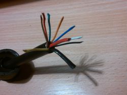
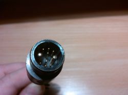
    I have an electric motor without a brush for a BLDC bicycle, which has two thick power cables and 7 thin cables (for Hall sensors and a temperature sensor, all 8 thin cables, but one white is not connected). Popular controllers for bicycle engines on the market require 3 thick power cords. Is there any way to rework this motor to control popular Chinese 3 phase wires? Photos of the motor and plug are sent in the attachment. Thank you in advance for your help. greetings
    BLDC 36v 250W electric motor for conversion of 2 phases into 3 phases BLDC 36v 250W electric motor for conversion of 2 phases into 3 phases BLDC 36v 250W electric motor for conversion of 2 phases into 3 phases
  • ADVERTISEMENT
  • #2 16982087
    Freddy
    Level 43  
    Here the controller is built into the engine - three thick wires (those with sleeves) come out.
    All you need is power and control.
    Is this driver damaged?
    You would have to modify the system to remove the electronics that is and use your own.
  • #3 16982153
    drvatican
    Level 13  
    Hello
    I have the engine without a driver for it. Now the question is whether it is better to leave it as it is and make the right driver yourself (I suspect it can be complicated, because there is probably some programmed processor controlling all this) or use the driver as it should be originally for this engine (only if they are somewhere available to buy for two power cables with Hall and temperature sensors?) or get rid of the original electronics and use a Chinese controller for 3 phase cables with Hall sensors and auto adaptation? What changes would I have to make to use Chinese for 3 phase wires?
  • ADVERTISEMENT
  • #4 16982195
    Freddy
    Level 43  
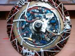
    You did not understand - this circuit board, which can be seen in the engine in the first photo, is the driver.
    See - I added descriptions in the picture.

    BLDC 36v 250W electric motor for conversion of 2 phases into 3 phases

    To control this engine differently, remove it from the plate that is in it.

    Look at my article on BLDC drivers. HERE .
  • #5 16982789
    drvatican
    Level 13  
    Hello
    Of course I understood, but for this engine that I have, you also need a driver with a microprocessor that reads signals from Hall sensors, am I wrong? The plug in the picture has 10 pins, so it's not enough to just give voltage to the motor, but you also need an additional driver.
  • ADVERTISEMENT
  • #6 16982795
    Freddy
    Level 43  
    Two thick power supplies are supplied to this plug, while the others can be used e.g. to connect a gas throttle, speedometer, etc.

    What exactly is the engine type?
  • #7 16982807
    drvatican
    Level 13  
    The hub sticker has the number 5MR88JDMTR436V250WT3VD1D0767 36V 250W, The driver's board inside the engine has the designation smcmeltonb0604. Date of manufacture 2011.01.03
  • #8 16982837
    Freddy
    Level 43  
    Is it bought from some Chinese? Is there a producer there?
  • #9 16982840
    Strumien swiadomosci swia
    Level 43  
    drvatican wrote:
    Chinese controllers for 3 phase conductors?


    You have outputs from the controller on a winding of 3 wires, but I would buy an ori driver for that.
  • #10 16982925
    Anonymous
    Anonymous  
  • #11 16982959
    Freddy
    Level 43  
    The controller will rather have a lever on the Hall effectors. This is a more popular and reliable solution.
  • #12 16982974
    Anonymous
    Anonymous  
  • #13 16983015
    Freddy
    Level 43  
    drvatican wrote:
    The hub sticker has the number 5MR88JDMTR436V250WT3VD1D0767 36V 250W, The driver's board inside the engine has the designation smcmeltonb0604. Date of manufacture 2011.01.03
    Show pictures of these hub stickers.
    See maybe there are some markings somewhere else.
    The plate is clearly visible.
  • ADVERTISEMENT
  • #14 16984851
    drvatican
    Level 13  
    Hello again.
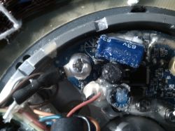
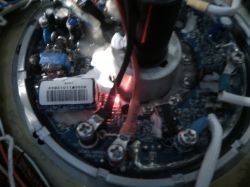
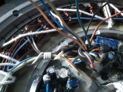
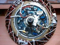
    Unfortunately, there is no manufacturer on the wheel or in the engine inside. I attach with the engine number in the attachment, but uncle Google spreads his hands and the lack of any information about this system. I did a little bit of wiring and the case looks as follows, except for two thick power cables +/- after unraveling the remaining bundle of the finally thin wires there are 6 and none of they have no connection to the controller ground. Two wires (of these six thin) in black and red on the controller board have a separate plug (see photo) and I suspect they may be for battery back charging (although I may be wrong because back charging can take place over thick power cables) Now yes, I have 4 wires left, which I consider as engine control and an ignition switch in orange, blue, yellow and green. After connecting the 36V voltage to thick power cables and short circuit (short circuit through the hand, i.e. a few mA or uA) of the yellow wire with the main power supply plus the red indicator starts blinking (see photo). Continue holding the yellow thin and red thick plus cables tightly by hand, by touching the green wire with your finger, the motor starts to rotate. So from what I determined yellow and red fat, the main plus is the start of the driver, i.e. the ignition switch and in this position by attaching the green cable to it is the throttle. Only now the question is, what resistance can a dry hand have and what resistor can be used to start the controller so that it does not fray? The same resistor will probably be connected to the throttle in series with the potentiometer, since the motor starts by shorting the cables through the hand (interesting fact, if I touch the green wire with a dry finger, the motor rotates slowly, if I saliva my finger the engine starts at full power ;) It remains to decipher thin cables (red and black with a separate plug on the controller, and blue and orange)
    Thank you in advance for the hints and greetings.
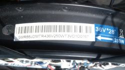
    BLDC 36v 250W electric motor for conversion of 2 phases into 3 phases BLDC 36v 250W electric motor for conversion of 2 phases into 3 phases BLDC 36v 250W electric motor for conversion of 2 phases into 3 phases BLDC 36v 250W electric motor for conversion of 2 phases into 3 phases
  • #15 16984881
    Freddy
    Level 43  
    You must experiment.
    Connect to these two thick 36V power supply and look if there is any voltage on thin cables, e.g. 5V.
    Where did you buy it from a Chinese?
    drvatican wrote:
    if I touch the green wire with a dry finger, the motor rotates slowly, if I lick my finger the engine starts at full power

    This indicates speed control ...
  • #16 16985325
    drvatican
    Level 13  
    I bought a wheel in Poland on a popular website with a broken power cable as damaged, I thought it was the standard that I would replace the wiring, connect the Chinese driver and I would be speeding, and here such circuses, after spinning the engine, it turned out that the whole controller is inside the engine. Strange that you can't see any control mosfets, but they are probably on the other side of the board and the hub housing serves as a heat sink, I don't want to pull it out because everything is covered with waterproof rubber. Could someone measure the resistance of a traditional gas throttle? Is there the potentiometer itself or any additional resistor? (i.e. what is the resistance at the min, and what at the max) I contacted the seller of this engine, they import used parts for electric bicycles from Germany, the engine probably comes from the Winora F1 comfortline bicycle, from what I was able to find this engine is called Winora Mionic PST and originally has an LCD display in the wiring, getting the original wiring probably borders on a miracle ;) also it keeps on figuring out how this system will properly run.
  • #17 16985558
    Freddy
    Level 43  
    There are various gas shifters - usually hallotron, but they can be potentiometric.
  • #18 19112532
    p.lagowski
    Level 1  
    Hello, I am refreshing the topic of such an engine, unfortunately after repairing the engine, the winding temperature sensor was lost, can you ask for a hint with which to replace the original one?
  • #19 19548964
    andrzej warchoł
    Level 10  
    I have a similar problem with a 24v 250 watt motor. The engine in the rear wheel of the Zokes 660 bike is about 15 years old. Only two black and red power cables are connected to the motor. In addition, two thin gray wires probably to the sensor.
    The wheel moves after applying voltage and short-circuiting the sensor wires, the rest disconnected from the damaged controller.
    I want to get information about the motor or is it a 2-phase brushless motor? Are these on the market?
    I am asking for a bit of understanding, because I am 76 years old and the topic is difficult for me .. but I want to solve it.
    I would like to replace a broken lever and driver with something.
    Heinzmann engine .. I couldn't find it.
    Thank you in advance for understanding.
  • #21 20664156
    pietrasten
    Level 1  

    Hello, I found this thread looking for the designation and function of the cables, and I know a bit about it. Moving from one apartment to another, I left the bike in the care of a friend, electric and the new ones. When he went, someone stole it that I didn't want to do anymore, and I took a broken bike from him. I say, and I'll fix it because I know a bit about it, and it was a UNION bike with the TRANS-X system. But mine is probably a newer model because I normally have three phases, three sensors hall in the same colors in the sense of yellow thick, yellow thin, blue thick, blue thin, green thick, green thin, brown thin, and white thin. And black and red thin as probably power supply, but knowing the trans-x system, I would not be so sure. Each company has some secrets. The first time I opened the driver of this company, it turned out that the phases do not go with colors as they should. Yellow went to green, green to blue, and blue to yellow. So better without testing with a meter, do not trust what you see. Greetings.

Topic summary

The discussion revolves around a BLDC (Brushless DC) 36V 250W electric motor that has two thick power cables and several thin cables for Hall sensors and a temperature sensor. The user seeks advice on how to adapt this motor for use with popular Chinese 3-phase controllers, which typically require three thick power wires. Responses indicate that the motor's internal controller is likely integrated, and modifications may be necessary to use a different controller. Suggestions include experimenting with the wiring to identify functions of the thin cables and considering the purchase of an original driver compatible with the motor. The user also shares details about the motor's specifications and the challenges faced in finding compatible components.
Summary generated by the language model.
ADVERTISEMENT