Elektroda.com
Elektroda.com
X

[Solved] Replacing the 3.5mm 4-pin Mini Jack in headphones with a microphone

Vende123 37113 10
This content has been translated flag-pl » flag-en View the original version here.
  • #1
    Vende123
    Level 9  
    Hello
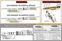
    Yesterday evening I had a problem with my Func hs-260 headphones. While moving the cable just under the cover of the jack, the headphones interrupted me until they stopped working. Today I wanted to prepare more or less a scheme for exchanging this plugin, but there is one problem.
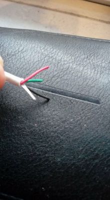
    The cable is attached to the headphones (allows the use of a microphone and audio) and is further divided into microphone and audio inputs. So how to solder the cables with the jack correctly? There are only three, red, green, WHITE FIBER, and black, when you need 4 wires for soldering.

    I attach additional photos to illustrate the situation:
    Replacing the 3.5mm 4-pin Mini Jack in headphones with a microphone Replacing the 3.5mm 4-pin Mini Jack in headphones with a microphone Replacing the 3.5mm 4-pin Mini Jack in headphones with a microphone
  • Helpful post
    #2
    krzysiozak
    Level 39  
    And no braid is tangled there [the screen]. As the fourth wire.

    You can ask for a photo of whole headphones.
  • #3
    Vende123
    Level 9  
    krzysiozak wrote:
    And no braid is tangled there [the screen]. As the fourth wire.

    You can ask for a photo of whole headphones.


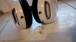
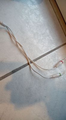
    Replacing the 3.5mm 4-pin Mini Jack in headphones with a microphone Replacing the 3.5mm 4-pin Mini Jack in headphones with a microphone

    As you can see, the microphone is also detachable. It is indifferent from which side it will be connected.
    And as for the fourth wire, I did not notice anything like that. Looking at the cable cut straightly, only three wires are available.
  • Helpful post
    #4
    krzysiozak
    Level 39  
    In the pictures you can not see how many individual plugs are there: [green and red] (3 pins) ?. And we are to understand that this cable was damaged next to the plug [4 pin]? Attached to the headphones.
    The headphone plug is probably demountable and you can view the connections.
  • Helpful post
    #5
    E8600
    Level 40  
    These wires are not a 2-strand case of each of these 3? Have you tried to gently remove the insulation from them?
    They can be varnished wires of different color of varnish.
  • #6
    Vende123
    Level 9  
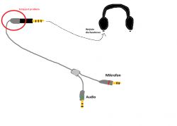
    Adds such an amateur scheme here to know where the problem is Replacing the 3.5mm 4-pin Mini Jack in headphones with a microphone

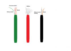
    And now yes, I checked these veins and there are actually several wires in them:

    -Black: Copper around white insulation, white insulation in which there is also copper (2)
    -Green: Green coated line, red varnished and plain copper (3)
    - Red: Only fiber (I checked 2x so I do not know why)

    Replacing the 3.5mm 4-pin Mini Jack in headphones with a microphone

    Now a little more is known, now the question is how to solder it?
  • Helpful post
    #7
    E8600
    Level 40  
    Vende123 wrote:
    -Black: Copper around white insulation, white insulation in which there is also copper (2)
    -Green: Green coated line, red varnished and plain copper (3)
    - Red: Only fiber (I checked 2x so I do not know why)


    In black, it's signal on the microphone and the copper braid is mass.
    In the green copper wire the remaining mass is the left and right channel (using the multimeter you check the left and right channel).
    Red is a normal nylon cable that prevents damage to the wire when stretched (it is not connected anywhere).
  • Helpful post
    #8
    krzysiozak
    Level 39  
    How would you like to upload photos from the work done. How does it look after soldering.
  • #9
    Vende123
    Level 9  
    E8600 wrote:
    Vende123 wrote:
    -Black: Copper around white insulation, white insulation in which there is also copper (2)
    -Green: Green coated line, red varnished and plain copper (3)
    - Red: Only fiber (I checked 2x so I do not know why)


    In black, it's signal on the microphone and the copper braid is mass.
    In the green copper wire the remaining mass is the left and right channel (using the multimeter you check the left and right channel).
    Red is a normal nylon cable that prevents damage to the wire when stretched (it is not connected anywhere).


    So what will the order of soldering on this Jack, looking at the pictures that I threw in the post?
  • Helpful post
    #10
    E8600
    Level 40  
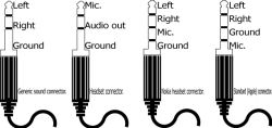
    Without measurements, you can only shoot. Probably it will be ok (if the plug is not in the Apple standard).

    Replacing the 3.5mm 4-pin Mini Jack in headphones with a microphone

    Like the description in black. The highest left and right channels can be swapped, but this should not disturb (you would have to check it with a multimeter).
  • #11
    Vende123
    Level 9  
    I bought new headphones. Repairing it was hard, for small soldering elements.