Hello.
For some time I have been planning to build a simple, cheap rotomat. One that it would be useful, and the funds are limited, and two (and probably more here) that I'm curious if I can do it, because I like DIY. However, I have huge gaps in electrical knowledge.
I took into account various solutions regarding the drive (old tape motors, cheap rotating display, microwave platter drive motor / has a nice function that it turns in a different direction each time it is turned on / etc.).
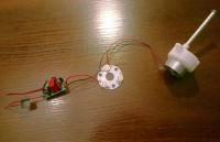
Now I have the drive system in my hand ... a disco light bulb.
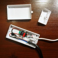
But this is where the questions come in. There is 230V to the system, 10.5V at the output of the PCB with the transformer, and only 2.7V at the input to the motor. There are 3 more colored LEDs along the way. As they are naturally unnecessary, what should I solder instead of them so that the motor gets the right voltage (some resistor?)? And are the cables at the board input too flimsy to provide 230V? Such were the factory ...
Another question is the possible magnetic field. There is no problem that most of this contraption is in a separate housing closer to the plug, but the motor must be next to the watch. The question is, how can a strong magnetic field produce such a weak motor (motor parameters unknown)? The watch itself is some distance from this motor (taking into account the motor mount, the device case, the axis of rotation, the second case which the watch will be in, etc.) so maybe this is a safe distance ...
The magnetic field can of course be checked with a meter, but it is again an investment and not knowing what values are considered safe for the watch and which are not.
So far I have worked on the first prototype. Everything works fine, but:
1) I do not know what to replace redundant diodes
2) I am not sure there is a possible magnetic field and hence I am concerned about putting a mechanical watch there
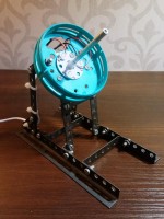
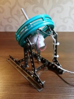
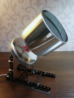
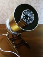
So far it looks like this:
Costs so far:
- mechanism removed from the rotary bulb - PLN 6.00
- construction made of Constructor elements (a toy from my childhood, 1987) - PLN 0.00
- cables from private supplies after broken devices - PLN 0.00
- housing after an old burnt electronic transformer - PLN 0.00
- a can of an old watch - PLN 0.00
- soldering tin, heat shrink bands, cable ties, electricity, my work, etc. - I don't know ... PLN 0.00
I am skipping the issue of the housing, finish and the switch as the next stage.
Please help me replace the diodes with something that will lower the voltage in front of the motor and how to measure or eliminate any magnetic field around the watch.
Thank you in advance.
PS I have already asked at Zegarkiclub.pl.


