FAQ
TL;DR: Chinese no‑name radios usually expose 5 key power/aux wires; “red - power after the ignition.” Map ACC/red, BATT+/yellow, GND/black, ANT/blue, ILL/orange to ISO A‑block safely. [Elektroda, Pedros050, post #17126292]
Why it matters: This helps DIY installers connect no‑brand head units without blowing fuses, losing memory, or miswiring.
For: Drivers fitting a Chinese radio to a car’s factory plug and ISO harness.
Quick Facts
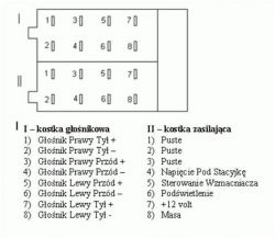
- ISO 10487 power pins: A4 = BATT(+), A7 = ACC, A8 = GND, A5 = electric antenna/remote. [“ISO 10487”]
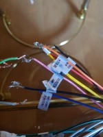
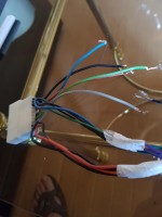
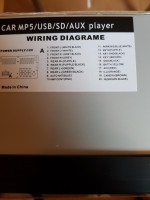
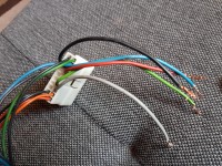
- Typical Chinese head units expose five leads: red (ACC), yellow (BATT+), black (GND), blue (ANT), orange (ILL). [Elektroda, Pedros050, post #17126292]
- Memory/clock hold requires constant BATT+ on A4/yellow, not the ACC line. [Elektroda, Pedros050, post #17126621]
- Edge case: Miswiring can blow the parking‑light fuse; replacing the fuse restored lights here. [Elektroda, Martineditt, post #17126561]
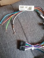
- Car‑side white plug and radio‑side black ISO plug interface; bridge them with an adapter harness. [Elektroda, Freddy, post #17126595]
What do the red, yellow, black, blue, and orange wires do on Chinese no‑name radios?
They are the core power/aux lines. Red is ACC/ignition. Yellow is constant BATT+. Black is chassis ground. Blue feeds a power antenna or antenna amplifier. Orange is illumination for backlight dimming. “red - power after the ignition.” Match these to the ISO A‑block. [Elektroda, Pedros050, post #17126292]
Which wire goes to ISO pin A4 for memory, and why?
Connect the radio’s yellow BATT+ to ISO A4. That constant 12 V keeps presets and the clock alive. If A4 lacks constant power, your radio will lose settings every key cycle. Tie ACC/red to A7 and GND/black to A8. [Elektroda, Pedros050, post #17126621]
My car has a white factory plug and my radio a black ISO plug—how do I connect them?
Use a vehicle‑specific adapter harness that mates the white car plug to a standard ISO plug. Then connect the ISO to your radio lead. This avoids cutting factory wires and keeps features like antenna control intact. [Elektroda, Freddy, post #17126595]
I have two black wires labeled GND and GND-. Should I tie them together?
No. Connect the main GND to chassis ground. Leave the GND‑ or secondary ground as the radio’s internal reference unless the manual instructs otherwise. “You’re only interested in … GND – the rest mass is in the back system.” [Elektroda, Pedros050, post #17126333]
I blew my parking‑light fuse after wiring the radio—what went wrong?
A miswire likely shorted a lighting circuit or mixed the illumination lead. Replace the blown fuse. Disconnect the orange ILL, verify ACC, BATT+, and GND with a multimeter, then reconnect ILL correctly. Re‑test lighting before finalizing. [Elektroda, Martineditt, post #17126561]
How should I connect ANT‑CONT and AMP on this radio?
Use blue ANT‑CONT to drive a power antenna motor or antenna amplifier. Use the AMP/AMP‑CONT (pink on some units) to switch an external amplifier. Do not combine them on one device. Labeling on your unit confirms these roles. [Elektroda, Martineditt, post #17126426]
How can I identify ACC and BATT+ without a diagram?
Use a multimeter.
- Set DC volts, black probe to chassis, red to each pin.
- Find constant ~12 V (BATT+). It reads 12 V with key off.
- Find switched ~12 V (ACC). It reads 0 V off, 12 V in ACC/ON.
Tape‑label both leads before connecting. [“Crutchfield: How to install a car stereo”]
Why do my presets reset every time I turn off the car?
The yellow BATT+ is not on a constant 12 V. Move the radio’s yellow wire to a true battery‑hot feed (ISO A4). Keep red on switched ACC (ISO A7). This preserves memory between drives. [Elektroda, Pedros050, post #17126621]
What ISO 10487 pins should I know for power?
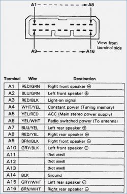
Remember the A‑block. A4 is constant BATT+, A7 is ACC/ignition, A8 is ground, A5 is electric antenna/remote. The A and B blocks together provide 16 pins (8 each), covering power and speakers. That layout speeds diagnosis and wiring. [“ISO 10487”]
Can I connect the orange ILL wire to ignition if I don’t need dimming?
Yes. Illumination can tie to the lighting circuit for dimming, or to ignition if you prefer full brightness. If unused, cap it safely. As one expert notes, it’s “at your discretion.” Confirm behavior after dusk. [Elektroda, Pedros050, post #17126292]
Do I need a Honda‑to‑ISO adapter for a Prelude IV?
Yes, use a Honda‑specific harness that plugs into the factory white connector and provides standard leads/ISO. A common example is Metra 70‑1720 for many 1986–2001 Honda models. It enables a clean, reversible install. [“Metra 70-1720”]
What’s the safest connection order to avoid shorts during install?
Prepare first. Disconnect the negative battery terminal. Identify and tape‑label BATT+, ACC, and GND on both sides. Make connections with crimp or solder, then reconnect battery and test. Only then hook antenna, AMP, and ILL leads. [“Crutchfield: Car stereo installation basics”]


