logo elektroda
logo elektroda
X
logo elektroda

Break in Robotic Mower Perimeter Wire: Finding & Repairing a 500m Cable with 3 Years of Use

mikiniki33 30156 44
ADVERTISEMENT
Treść została przetłumaczona polish » english Zobacz oryginalną wersję tematu
  • #31 19482814
    kriss032
    Level 21  
    kotbury wrote:
    As for the signal - for me, the NAC quinola base transmits with a frequency of 7.78 kHz (which is even less than long), amplitude 270 mV, more or less rectangular shape.

    Cables that are close to each other but in opposite directions cancel each other out (something like a bifilar coil). Please provide a picture of the wiring layout.
    And as for the fields - it's strange that there are none. My chino MA! and "until" 4 fields. But not with any GPS, I just demarcate them with very narrow passages, and he just "programs" which he is supposed to enter - he remembers the time of driving along the perimeter cable and "detaches" from it after that time - simple as a balloon.
    And at first I was wondering - how does it know which way to go to the base - it turned out that after the battery runs out, it starts spinning in circles a few times (supposedly to fill the base, but it comes out terribly badly), then it goes straight ahead and when it encounters a wire, it ALWAYS turns right and follows it to the base.
    The base, of course, must be set with the entrance to the left, of course there is no information about this in the instructions and of course I set it the other way around.

    Bangla OK now. One note - if the charging starts to go crazy (i.e. 10 minutes of driving, half a day of charging) it's not the fault of the dead batteries but the poor connectors of the cables from the battery to the motherboard - they get hot - I had to correct it in my and two other NACs of my friends. All Chinese - there is a 60-amp XT60 in the battery, a plug on the board with pins as thick as a pin.
    Thank you for the information. I am a newbie in the subject. I will shortly send a connection diagram of three fields to a mower that does not have it in the program (it returns to the base from each field) for now I have it in my head I have to draw it

    Added after 30 [minutes]:

    Thank you for your knowledge. I bought a cheap Mac Alister 500m2 mower, the bigger one in Castorama. I am a novice in the subject of robot mowers, a diagram of how to divide a complicated lawn into two or three fields for a simple mower without a brain Mac Alister without a field division program, I will draw a diagram in my head and send it (the mower returns to the base by itself from each field) The mower charges over an hour and he works 1.5 hours to return to the base.

    Added after 15 [minutes]:

    Someone asked what the word stupid means I bought a connector in a store once it connected once it didn't block and gave me money back I bought it a second time on Alle it was too expensive and it got blocked I returned it they are supposed to return the money, apparently the whole series is falling apart I bought two more connectors on They all work hard
  • ADVERTISEMENT
  • #32 19489286
    kriss032
    Level 21  
    Due to the questions, I finally had time to draw a diagram during assembly I had it in my head. Wiring diagram of the guide line cable of the Mac Alister 500 m2 robot mower, divided into two fields (the mower does not have a field division program) the fields can also be additionally divided, I have a complicated lawn with numerous niches, even a 1500 m2 mower will not be able to leave tufts of grass unmown
  • ADVERTISEMENT
  • #33 19489296
    Krzysztof Kamienski
    Level 43  
    @kriss032 16 Amp cam switch.....It made me ..twisted :cry: .... What current flows through this wire-antenna? You couldn't put a relay in there and even remotely control it?
  • #34 19501816
    kriss032
    Level 21  
    I know that I overshot 16A is a bit too much, There are a few milwatts of Wcz current in the mower's wire. I needed hermetic switches to be installed outdoors in damp conditions and only such I found CAM SWITCH 16A 3F 1-0-2 IN IP65 HOUSING or CAM SWITCH 16A 3F P-0-L IN IP65 HOUSING. But ............ I installed the first connector the next day it broke I installed the second connector jammed in a moment I replaced it with the third connector also failed the connectors were purchased from different sellers it seems that the whole series is fake. The sellers returned the money without hesitation, they probably knew what they were selling. I wasted two weeks of time and connected the wires briefly 2x6 pieces 1 field in front of the house 2 fields behind the house plus dividing the second field in half. I learned it by heart. The mower from the description covers a field of 500 m2, there is no division of fields in the program, my lawn is 500 m2, it is not in the shape of a square, it is intricate and complicated, it has many niches. It needs a mower for 1500 m2. Later, I installed 6-pin right-left connectors for PLN 9 each and they work, they are not hermetic after winter, I will probably have to replace them.
  • #35 19502732
    Jacek Rutkowski
    Level 28  
    Connectors physically blocked or stopped connecting?
    16A connectors have contacts designed for high currents.
    At milliamperes, there is no burn-in effect of tarnish on the contacts and the contacts must be gold-plated, etc.
  • #36 19503303
    kriss032
    Level 21  
    One switch was jammed after installation, the other switch was also jammed, I turned it as if I could force it, but it started to jam and creak when switching, it made a sound as if the contacts had fallen apart, it walked with resistance. All connectors worked after installation and began to have contact breaks after an hour or a few days. Please write more clearly what the effect of burnt contacts means.
    Are these contacts not suitable for low Wcz currents in mowers?

    Added after 17 [minutes]:

    I had a similar case with a 3F 16A wall-mounted on-off socket in one housing plus a single-phase socket switched off with the same switch, only that 0-1 was blocked after half a year, I replaced the socket with a different type of switch and it's been ok for two years. After dismantling the socket, the wires were only 2.5 square meters too small to power a device that consumes 3.5 KW for 4 hours
  • ADVERTISEMENT
  • #37 19503521
    Krzysztof Kamienski
    Level 43  
    @kriss032 I don't understand it at all.16 A :cry: ..... any 12 volt relay, inserted into a hermetic can, if you absolutely want to bury it, e.g. and remotely switch it by applying voltage to the relay from even a penny power supply for LEDs. What about a simple rocker switch? There are also versions with a rubber cover.
  • #38 19503785
    stomat
    Level 38  
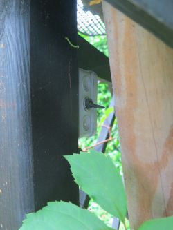
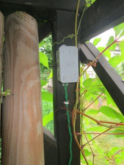
    I have a similar solution, but I used an ordinary toggle switch in a plastic housing from the market. I have wires from the lawn led to the leg of such a gazebo and I exclude a certain zone from the operation of the mower. So far I haven't had any problem.
    Break in Robotic Mower Perimeter Wire: Finding & Repairing a 500m Cable with 3 Years of Use Break in Robotic Mower Perimeter Wire: Finding & Repairing a 500m Cable with 3 Years of Use
    It is in the down position - i.e. the excluded zone, the mower does not enter part of the lawn, I can put various objects there, e.g. cut branches.
  • #39 19505610
    Jacek Rutkowski
    Level 28  
    kriss032 wrote:
    Please write more clearly what the effect of burnt contacts means.
    Are these contacts not suitable for low Wcz currents in mowers?

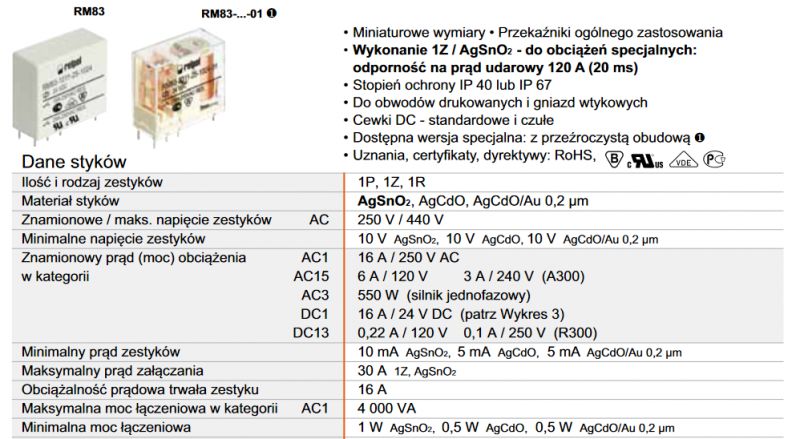
    High-current contacts are made of refractory materials, which become covered with oxides after some time.
    These oxides are a break for low voltages, which burn out only at appropriate currents.

    In the better catalogs, the minimum currents are given, which ensure the burnout of the oxides:
    Break in Robotic Mower Perimeter Wire: Finding & Repairing a 500m Cable with 3 Years of Use
  • ADVERTISEMENT
  • #40 21100844
    Przemekprzemek
    Level 12  
    I dig because I have a way (primitive and stupid ,, but it works )
    Today the same thing happened to me , after a long disassembly of the base because of elevation work I reconnected the base today and the problem appeared no loop , I read the thread about radios, etc, but for me it is unbearable so I came up with a rather stupid in simplicity how to quickly diagnose the broken loop of about 500m, to check you need a meter set to transition / diode, extension cord and a thin tailor pin , I unplugged one end of the loop and plugged it into the extension cord (not plugged in of course) with the extension cord I went about halfway through the loop, exposed the lawnmower wire I stuck the pin in and the meter beeped , , insulated the cable , then I divided the remaining loop in half again and did the same, the meter beeped, again divided the remaining part in half, stuck a pin and quiet aha,, and I found without a problem, the search time 5-8 minutes ,,,
    probably specialists will not like this....
    greetings
  • #41 21100862
    kotbury
    Gantry automation specialist
    It doesn't even go that you won't like it.... , at my place the cable was partly in the grass but partly buried, and with my patience I had when looking for it and digging it out I was 100% sure that I would cut it, so I preferred to seek the help of the radio and if necessary to pinch it where it was already disturbed. And I couldn't imagine digging it out at least 4 times, each time panting that I would damage it.
    And the cable is green, quite thin (surprisingly, the Chinese probably made a mistake to its detriment - there is a lot of copper there - practically unbreakable by hand, the insulation is also specifically flexible) so finding it was also problematic.
  • #42 21102083
    Jacek Rutkowski
    Level 28  
    Przemekprzemek wrote:
    I'm digging because I have a way (primitive and stupid , but it works )
    Today the same thing happened to me , after a long disassembly of the base because of elevation work I reconnected the base today and the problem occurred no loop , I read the thread about radios, etc, but for me it is unbearable so I came up with a rather stupid in simplicity how to quickly diagnose the broken loop of about 500m, to check you need a meter set to transition / diode, extension cord and a thin tailor pin , I unplugged one end of the loop and plugged it into the extension cord (not plugged in of course) with the extension cord I went about halfway through the loop, exposed the lawnmower wire I stuck the pin in and the meter beeped , , insulated the cable , then I divided the remaining loop in half again and did the same, the meter beeped, again divided the remaining part in half, stuck a pin and quiet aha,, and I found without a problem, the search time 5-8 minutes ,,,
    probably specialists will not like this....
    greetings

    I met with the application of 230V to one end and a meter with a long insulated handle pin to one end and the other in the hand on the AC range. Near the fault it hit 50-70V :) A friend tested after rain in rubber boots :) .
  • #43 21102119
    Krzysztof Kamienski
    Level 43  
    Jacek Rutkowski wrote:
    Friend tested after rain in rubber boots
    He should from the deck of a hovercraft.
  • #44 21102292
    Przemekprzemek
    Level 12  
    Jacek,,,,
    well that's a brave step,,, I have differentials all over ,, it wouldn't work at my place ,, and probably even good....
  • #45 21103747
    Jacek Rutkowski
    Level 28  
    Przemekprzemek wrote:
    Jacek,,,,
    well that's a brave step,, I've got a differential on the whole ,, at my place it wouldn't work ,, and probably even good..


    A friend had 2 230/12V 200VA trays spliced as an isolation trafo so the differential wouldn't trigger....

    Generally such a patent can whip the wire as somewhere along the way the insulation is also damaged and there is the problem that you can miss the point of damage as it will not hiss and cook the wire on the damage....

Topic summary

The discussion revolves around locating and repairing a break in the perimeter wire of a robotic mower, approximately 500 meters long, after three years of use. Various methods are suggested for detecting the break, including applying mains voltage to the wire ends and using a field sensor, checking resistance with a multimeter, and utilizing AM radios or specialized cable finders. The challenges of finding the break due to the wire's proximity to the surface and potential interference from moisture or other factors are highlighted. Users share personal experiences and techniques, emphasizing the importance of careful handling to avoid further damage to the wire during repairs.
Summary generated by the language model.
ADVERTISEMENT