Elektroda.com
Elektroda.com
X

Cable repair in the wall for years - that is, roast me electrode :)

2P 117201 92
This content has been translated flag-pl » flag-en View the original version here.
  • Cable repair in the wall for years - that is, roast me electrode :)
    I tried very hard ... renovation, finishing, tiredness ... hit me too.
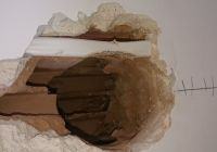
    The cable is cut solidly, in such a stupid place that I am ashamed to admit that I marked the place for a new box myself. Let's do it for fatigue and that's the end of the topic.

    I decided to document the repair process so as to take advantage of this fact and officially write on the electrode how, in my humble opinion, you can properly connect the cables in the wall, if you want to avoid the box. The subject is called "roast me" because I know what writing about THESE things on the electrode can be.

    Luck - the condition is such that I can easily remove and replace the cable part for the top box.
    I decided to deal with the matter systematically and neatly.

    For various reasons, I did not want to connect the cable in the box. Cables for the socket circuit in the kitchen, so the nominal load of 16 A is quite real. I decided to start the repair properly so that I could easily forget about the problem.

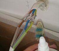
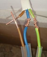
    Cable cut, peeled about 2 cm of wires. The cable is cleaned of rubbish with a cleanser.
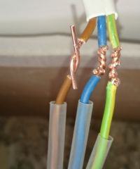
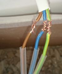
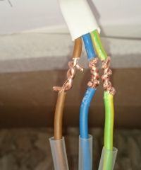
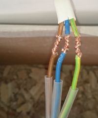
    And a twisted pair recommended by some, and a condemned by others, and how to make it, to the best of my knowledge, properly:
    Cable repair in the wall for years - that is, roast me electrode :) Cable repair in the wall for years - that is, roast me electrode :) Cable repair in the wall for years - that is, roast me electrode :) Cable repair in the wall for years - that is, roast me electrode :) Cable repair in the wall for years - that is, roast me electrode :)

    I would like to add that the cable is 2.5 mm?, so it was not twisted with your fingers. In this case, I recommend two pliers or pliers - one holds and the other curls.

    I have a liking for the part of the forum in favor of a twisted pair? Or maybe the twisted pair is not like that? I admit that I pulled the zero cable slightly - I caused a part of the cable to break some 3-4 mm from the end. I have already decided to forgive this mistake and not take everything apart.

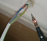
    Well, now supporters of the twisted pair will begin to thunder - I do not trust the twisted pair for the sockets, there is such a machine:
    Cable repair in the wall for years - that is, roast me electrode :)
    By the way - I highly recommend this solution. From getting to know gas soldering irons, I don't want to look at transformer tubes anymore. I do not know a more convenient solution (in field conditions).

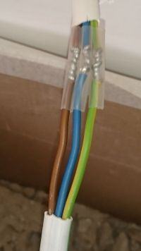
    And soldered:
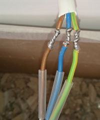
    Cable repair in the wall for years - that is, roast me electrode :)

    Further no surprise - cleaning:
    Cable repair in the wall for years - that is, roast me electrode :)
    After cleaning - you probably don't see much difference in the photo, but the flux residues have been thoroughly removed:
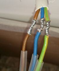
    Cable repair in the wall for years - that is, roast me electrode :)
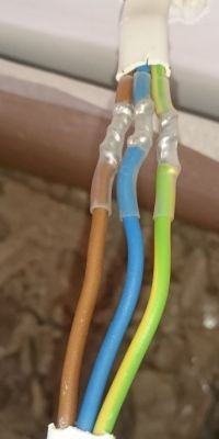
    And putting on T-shirts:
    Cable repair in the wall for years - that is, roast me electrode :) Cable repair in the wall for years - that is, roast me electrode :)

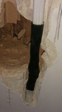
    The final T-shirt to recreate the outer insulation is a T-shirt with an adhesive:
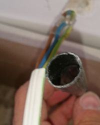
    Cable repair in the wall for years - that is, roast me electrode :)

    The final result:
    Cable repair in the wall for years - that is, roast me electrode :)

    Cool? Ranking DIY
    About Author
    2P
    Level 20  
    Offline 
    2P wrote 345 posts with rating 197, helped 22 times. Live in city Zabierzów. Been with us since 2004 year.
  • #2
    czareqpl
    Level 33  
    Generally cool, I recommend cutting individual veins in different places in the future. So that in the event of an abrasion of the heat-shrink, you can still lean on the original needle.
  • #3
    haderach
    Level 28  
    czareqpl wrote:
    I recommend cutting individual veins in different places

    Me too.
    Besides, I give two heat-shrinkable sleeves for the core and the outer one with adhesive.
  • #4
    Wojtasson
    Level 10  
    The cables should not be soldered, but clamped with Wago connectors, or screwed with some screw connectors.
    Tin Sn63Pb37 melts at 183 ° C, if you count how much the resistance has increased at this point, it will turn out that quite a small current can melt the connection.
  • #5
    czareqpl
    Level 33  
    Wojtasson wrote:
    Cables should not be soldered, but clamped in a balance or screwed with some screw connectors.
    Tin Sn63Pb37 melts at 183 ° C, if you count how much the resistance has increased at this point, it will turn out that quite a small current can melt the connection.


    Remember that the resultant resistance of the twisted and additionally soldered wires has a lower resistance than the rest of the wire. So, to force a temperature of 183 degrees at the junction, the remainder of the strand should be over 200 degrees ...

    If the rest of the installation is in accordance with the standard, it is impossible to force a current that will raise the temperature of the cable to 183 degrees.
  • #6
    Łukasz.K
    Level 28  
    Yes, soldering usually gives a more durable connection than twisting or other inventions - in my opinion. As long as the working temperature of the brazed place does not exceed 100 degrees. C. As far as I know, the solder melts at about 150 degrees Celsius. C. and when it comes to connections that heat above 100 degrees Celsius. C then I would not recommend soldering. You can also twist the cubes to a greater cross-section than the connected wires (for installation connections). So that both wires to be connected go through the entire metal part of the cube, but do not protrude beyond the orange part of the insulation. Then we have a very fast and very durable connection (pressed with screws at two points). The resistance at the point would increase, as one colleague wrote, if it were a point, but it is not a point but a surface with such a high value that the contact resistance through the solder is negligible compared to the resistance of the conductor resulting from its cross-section. So in this case, due to the large contact surface, its resistance is small and basically only the conductor cross-section counts (two, because two wires are twisted, i.e. R one / 2). and as long as the connection is properly soldered, i.e. wires wetted with tin without cold solders, because copper dissipates heat very well, besides, my colleague above rightly wrote that there is less resistance in the place of soldering because the cross-section is larger, the binder itself dissipates heat and gives off a greater part heat of copper, and this disperses it to the environment and nothing will dissolve there until the copper wire warms up to over 100 degrees. C. However, generally, most professionals use bolted connections. Among other things, because they are fast and very reliable (turning at two points).
  • #7
    rb401
    Level 38  
    2P wrote:
    but the flux residues were thoroughly removed


    If the type of flux used needs to be removed, the use of such flux in this application makes no sense. Because it cannot be removed 100% with such washing (it will be pulled under the insulation).
    And if the flux is "no clean" and it is supposed to be "cosmetic", it also makes no sense here.


    2P wrote:
    I have a liking for the part of the forum in favor of a twisted pair?


    As for the twisted pair just here and with such a wire, I have mixed feelings. It doesn't look nice, you can easily strain the wire, though it works. Especially since it's only three wires and not some bigger work.
    But if you were to insist on the "professional" level or it was about a large number of such connections, then I would consider a technology that may already be a bit fading, namely the use of tinned wire springs or silver plated.
  • #8
    Łukasz.K
    Level 28  
    The wires can be twisted, but relatively gently, with feeling, because if we twist too much, the wire may break at an unexpected moment when soldered. :cry: . If someone wants to remove flux, I recommend acetone or nitro solvent, but I don't know why. Be careful not to damage the cable insulation with the solvent.
  • #9
    oskar777

    Level 26  
    And there were no special copper sleeves used for this, plus a special crimping tool for them?
  • #10
    kortyleski
    Level 43  
    Then count the area of the connector in the crimped sleeve and the area of the soldered twisted pair.
  • #11
    polaklbn
    Level 24  
    kortyleski wrote:
    To count the area of the connector in the crimped sleeve and the area of the soldered twisted pair.


    If you write like this then I could not forgive myself not to reply to your post.

    Now please "Calculate the area of the connector in the Wago cube, screw cube, twisted and soldered wires" and refer to the performance of electrical installations and more specifically their connections. It turns out that Wago it has the smallest contact surface, yet it is the best way to make connections in low voltage installations.

    What's more, "muff" done by the author is made almost correctly.
    It is because you should "twist" on different sections, as it has already been mentioned.

    For this purpose, I use compression sleeves in the case of lines, while in the case of wire, they are made by a technique similar to the technique of the author of the topic.
  • #12
    kortyleski
    Level 43  
    polaklbn wrote:
    Wago has the smallest contact area, yet it is the best way to make connections in low voltage installations

    It is not the best. It is one of the easiest ways.
  • #13
    polaklbn
    Level 24  
    kortyleski wrote:
    It is not the best. It is one of the easiest ways.

    And what do you think he is best way ?
  • #14
    czareqpl
    Level 33  
    polaklbn wrote:
    For this purpose, I use compression sleeves in the case of lines, while in the case of wire, they are made by a technique similar to the technique of the author of the topic.


    That's it. There is nothing to connect to the contacts in the order of fractions of mOhm, since the permissible current in the line will not exceed 32 A.
    Better look at biodegradable harnesses in new cars, what are the voltages and what control currents ... Fan: 5 A, Air conditioning solenoid: 3 A, Xenon: 7 A, Alternator: 70 A, ...
    There the bundles get an impression, cold, hot, wet, salt ...

    In the case of the cable in the pictures above, it will have super comfortable working conditions.
  • #15
    polaklbn
    Level 24  
    czareqpl wrote:
    polaklbn wrote:
    For this purpose, I use compression sleeves in the case of lines, while in the case of wire, they are made by a technique similar to the technique of the author of the topic.


    That's it. There is nothing to connect to the contacts in the order of fractions of mOhm, since the permissible voltage in the line will not exceed 32A.
    Better look at biodegradable harnesses in new cars, what are the voltages and what control currents ... Fan: 5A, Air conditioning solenoid: 3A, Xenon: 7A, Alternator: 70A, ...
    There the bundles get an impression, cold, hot, wet, salt ...

    In the case of the cable in the pictures above, it will have super comfortable working conditions.


    I agree with you, but comparing AC electrical installations and DC automotive installations are two different fairy tales, governed by their laws and regulations regarding their performance, operation and maintenance.

    Somehow I cannot imagine performing comprehensive measurements in a single-family building, in which the wires have been soldered together. In order to correctly eg find a fault in a given installation, I will have to "start it up". Twisting again may involve breaking the wire, which will lead to forging the wall so that I can put on, for example, a candlestick connector.

    Despite the above, I would not accept a different connection in this case than the one presented by the author of the topic (unless crimp sleeves).
  • #16
    2P
    Level 20  
    I will take advantage of the fact that I have a moment at work when "everything happens by itself" and I will refer to a few, really factual statements.
    Let me skip the weight and ankle discussions - I use them myself, but only in cans.

    czareqpl wrote:
    for the future, I recommend cutting individual veins in different places.
    Yes - I thought about it myself, but it was already a little late ... however
    czareqpl wrote:
    So that in the event of an abrasion of the heat-shrink, you can still lean on the original needle.
    Here I cannot agree - if the T-shirt is worn, it will resist the other T-shirt. Anyway, the cable in the wall does not work - there is nothing to rub. This shift is about something completely different: the thickness of the entire muff. Just by making the connection in one place, we will have a solid thickening.

    haderach wrote:
    Besides, I give two heat-shrinkable sleeves for the core and the outer one with adhesive.
    I would do it if I was repairing an extension cord, for example ... But the cable in the wall? I guess a bit exaggerated.

    Wojtasson wrote:
    Cables should not be soldered, but clamped in a balance or screwed with some screw connectors.
    Tin Sn63Pb37 melts at 183 ° C, if you count how much the resistance has increased at this point, it will turn out that quite a small current can melt the connection.
    In the presented solution, it is the twist that conducts the largest part of the current. Brazing only improves the quality of the joint, prevents oxidation and stabilizes mechanically. Doubts are probably dispelled by a rather accurate comment by czareqpl.

    rb401 wrote:
    It doesn't look nice, you can easily strain the wire, though it works. Especially since it's only three wires and not some bigger work.
    As for the nice appearance - tastes are not discussed. What is a wire strain - right ... you have to be careful because the pliers give a huge leverage for such a job. As for the bigger work - it's all a matter of price ... but the fact that I would not do the installation. Too much hassle. In general, it is much easier to make a twist when the wires come out in one direction, but then it is more difficult to put on a T-shirt. Such a twist where the wires go in opposite directions is, to me, one of the most annoying twists to be made. But this is a single "at home" repair so I could afford to get tired of it.

    There were a few questions about the flux - it is rosin, which was originally in tin + "no clean" liquid flux. Yes - a little art for art. It's more about the T-shirts catching well.
  • #17
    haderach
    Level 28  
    rb401 wrote:
    use of tinned wire springs or silver plated.

    You mean something like this ?:
    Cable repair in the wall for years - that is, roast me electrode :)
    This is what I usually do in case of failure, a wrapper about 2 cm long and soldering.
  • #18
    kortyleski
    Level 43  
    polaklbn wrote:
    Somehow I cannot imagine performing comprehensive measurements in a single-family building, in which the wires have been soldered together. In order to correctly eg find a fault in a given installation, I will have to "start it up".

    What have you eaten?
    Do you develop canned twisted pair too? Do you unbutton the weight The repair performed in this way is treated as a uniform cable, it has a beginning and an end. And already.
    polaklbn wrote:

    And what do you think is the best way?

    Everyone likes something different. I prefer a properly made twisted pair. Of course, a professional electrician will choose Wago because it is faster. Or a Wago replacement because it's fast and inexpensive. And if someone does it at home, it will twist and solder. The house will collapse sooner than such a joint will be released.
  • #19
    haderach
    Level 28  
    kortyleski wrote:
    The house will collapse sooner than such a joint will be released.

    And here you are right :)
    However, I also do not understand:
    polaklbn wrote:
    Somehow I cannot imagine performing comprehensive measurements in a single-family building, in which the wires have been soldered together
  • #20
    polaklbn
    Level 24  
    kortyleski wrote:
    What have you eaten?
    Do you develop canned twisted pair too? Do you unbutton the weight

    When measuring or locating a fault, of course, I unfold the Wago and unfasten it. Wago connections give me the ability to do this without damaging the veins.

    haderach wrote:
    However, I also do not understand:
    polaklbn wrote:
    Somehow I cannot imagine performing comprehensive measurements in a single-family building, in which the wires have been soldered together

    kortyleski wrote:
    The repair performed in this way is treated as a uniform cable, it has a beginning and an end. And already.


    polaklbn wrote:
    Despite the above, I would not accept a different connection in this case than the one presented by the author of the topic (unless crimp sleeves).


    I wrote about canned connections etc, not repairing wires :) !

    My deliberations on connections (not only in the situations presented by the author) were aimed at drawing attention to this statement:
    kortyleski wrote:
    To count the area of the connector in the crimped sleeve and the area of the soldered twisted pair.

    The contact area in the place of damage, before damage, was 2.5 mm?. After repair, it is larger and it is highly recommended.
  • #21
    Jawi_P
    Level 35  
    polaklbn wrote:
    I wrote about canned connections etc, not repairing wires :) !

    Then don't write off topic and you will be understanding.
    Because the post is about "REPAIR" even in the topic. The electrician during the measurements does not know about such a repair. And if the measurement is bad for him, what's the difference whether a damaged section of a cable is not repaired or repaired, and both need to be replaced.
  • #22
    polaklbn
    Level 24  
    Jawi_P wrote:
    And if the measurement is bad for him, what's the difference whether a damaged section of a cable is not repaired or repaired, and both need to be replaced.


    And here you are wrong. Because if the measurement goes wrong on a given circuit, I do not replace all the wires of a given circuit, but I try to locate the "section" of the circuit between its individual connection points (e.g. box - connector, connector - housing) and this is where the need arises " unfasten "connections. So my statements are not quite right off the topic .
  • #23
    Tomasz Downacki
    Level 13  
    Once, when I read the statements of some Janusz from this forum, in the event of damage to the insulation, the installation must be replaced up to the main transformer in the estate.
    I myself have soldered and insulated. It has been good for several years.
  • #24
    Jawi_P
    Level 35  
    2P wrote:
    For various reasons, I did not want to connect the cable in the box.
    polaklbn wrote:
    And here you are wrong. Because if the measurement goes wrong on a given circuit, I do not replace all the wires of a given circuit, but I try to locate the "section" of the circuit between its individual connection points (e.g. box - connector, connector - housing) and this is where the need arises " unfasten "connections. So my statements are not entirely off topic.

    You can still do what you describe, no one is suggesting you to replace the mains with the transformer as inaccurately suggests
    Tomasz Downacki wrote:
    Tomasz Downacki
    . (By the way, can you point to such a post? Because many may feel offended. Maybe you took the sentence out of context?)
    This is a section of the cable that is normally under the plaster, because the author originally drilled a hole for a new box. As I understand from the photos above, it's not for this cable?
    Because if it was supposed to be for this cable, I would rather break it up and down and do what the author did and leave the connector in the box. Or, if the conditions and distances allow it to move the can up or down and replace one of the sections. Since there is renovation, mess etc. Even a lot of forging would not be there, because the old cable furrow will remain, only improve it. If it was supposed to be decent.
  • #25
    2P
    Level 20  
    Jawi_P wrote:
    This is a section of the cable that is normally under the plaster, because the author originally drilled a hole for a new box. As I understand from the photos above, it's not for this cable?
    Exactly. A box for an independent cable pulled directly from the switchgear. As if it was a box for a cut cable, I would just move it slightly - there would be a bit of gymnastics due to the short wires, but everything could be easily folded on WAGO or on ankles ... or on twisted-pair ... wounds - whatever - no let's unleash a new storm about what is best for connecting cables in boxes.

    Despite the fact that those who argue about it will probably not read it anyway (just like they have not read the topic), but let's detail that it is about repairing a damaged cable. I am not persuading anyone to do such an installation. And apart from all aspects of measurements, the possibility of modification (although these are important aspects, but not in this thread) ... it is not worth miraculous in a box that will be relatively easy to access in the future.
  • #26
    colok
    Level 11  
    Crimp connections are more durable than soldered connections, however. This is how practice shows.
    Over the years, the tin oxidizes and the junction resistance changes. It starts to heat up, sparkles and burns out.
    It was, is and will be.
  • #28
    walbe
    Level 18  
    colok wrote:
    Crimp connections are more durable than soldered connections, however. This is how practice shows.
    Over the years, the tin oxidizes and the junction resistance changes. It starts to heat up, sparkles and burns out.
    It was, is and will be.

    After how many years?
    Should electronic devices with soldered elements on the PCBs disintegrate after years, heat and spark?
  • #29
    misiek1111
    Level 32  
    colok wrote:
    Over the years, the tin oxidizes and the junction resistance changes.

    Say that to my several hundred home calls that are already 23 years old :-)
  • #30
    lukiiiii
    Level 29  
    My 3 cents for discussion:

    by wikipedia:
    substance; specific conductivity

    copper 58.6 10 ^ 6
    Sn 63% Pb 37% approx. 6.9 ? 10 ^ 6

    It turns out that this tin is not so perfect, but ... at home in 2006, I made such a connection in the place of the liquidated kitchen socket. This circuit fed the entire kitchen. This place was then tiled too. In 2013, during the renovation, I took a close look at this connection, even cutting it with pliers to see the cross-section. Nothing happened there.

    polaklbn wrote:
    Somehow I cannot imagine performing comprehensive measurements in a single-family building, in which the wires have been soldered together


    There is a discussion about fixing a cable in the wall, does a colleague cut wires in the wall during measurements? :)