logo elektroda
logo elektroda
X
logo elektroda

Selection of the diameter of copper pipes in the central heating installation

seamen1978 11547 10
ADVERTISEMENT
Treść została przetłumaczona polish » english Zobacz oryginalną wersję tematu
  • #1 17180637
    seamen1978
    Level 2  
    Hello all,
    I plan to replace the old central heating installation from steel with copper and replace old radiators. Two different plumbers suggested two different pipe sizes and radiators.
    The house has an area of approximately 110m2. the usable area is well insulated, I do not count the basement which is at ground level because there will be no radiators in it.
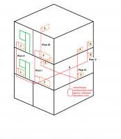
    On the middle floor there is a 28 m2 living room, a 13 m2 kitchen, a bathroom (with a bathtub) and a corridor, and on the 1st floor there is 3 rooms, approximately 14 m2 each, a bathroom (with a shower and a corridor. There are 5 radiators on each floor).
    Total: 13474W
    The stove is located in the basement and from it along the ceiling there are 5 "threads" to the risers and unfortunately it is not possible to change this arrangement. The furnace will be condensing, single-function by Saunier Duvall Thelia Condens 18kW and a container with a capacity of 150l by BIAWAR QUATRO.
    RISER I, II, III, IV: pipes "run" under the ceiling to each of these risers, the distance from the furnace to the riser is about 6 meters, then each riser is about 3.5 meters, the distance from the riser to the radiator is about 80 cm
    V VERTICAL (bathroom): distance from the stove to the riser: 2.5 meters, height of the riser about 3.5 meters:
    1) One plumber's suggestion: Horizontal pipes from the stove to the risers, 28mm pipe, 22mm risers, 18mm radiator connections, return 22mm, and claims that 4 cast iron radiators that are on the top floor should not be replaced ...

    2) A suggestion from the second plumber: horizontal pipes from the furnace to the risers 22mm pipe, 22mm risers, 15mm radiator connections, 22mm return
    The proposal for the selection of radiators is similar for both men:
    Radiators Nr.1 type C33: 3 pieces, each with a power of 1318W, a total of 3954W
    Radiators Nr.2 type C32: 5 pcs, each with a power of 1750W, a total of 8750W
    No.3 bathroom radiators: 2 pieces, each with a power of 435W, a total of 770W
    Total: 13474W
    I would like to ask for an evaluation / comment / advice regarding the choice of both men.
    Thank you in advance
  • ADVERTISEMENT
  • Helpful post
    #2 17180657
    vodiczka
    Level 43  
    seamen1978 wrote:
    The stove is located in the basement and from it, along the ceiling, 5 "threads" to the risers are distributed
    Each pawn has its own thread? Then I don't see any point in changing the cross-section when going from horizontal to vertical.
  • ADVERTISEMENT
  • #3 17180756
    seamen1978
    Level 2  
    vodiczka wrote:
    seamen1978 wrote:
    The stove is located in the basement and from it, along the ceiling, 5 "threads" to the risers are distributed
    Each pawn has its own thread? Then I don't see any point in changing the cross-section when going from horizontal to vertical.


    Thanks for the answer, what do you think about these diameters?
  • Helpful post
    #4 17180803
    vodiczka
    Level 43  
    I am not an installation professional. Larger diameter = higher investment cost but lower flow resistance, i.e. the pump will use less energy to transport the same amount of liquid. I don't understand why there should be larger diameters on the return than on the supply? The larger diameter of the pipes should be used when supplying risers significantly further away from the boiler than others or with a greater number of radiators. Let the experts speak with capital F.
    On the net, a strange confusion about the topic of "choosing the diameter of pipes for what" :)
  • Helpful post
    #5 17180846
    Sstalone
    Level 31  
    Buddy, you should have an installation project. Who was drawing it to you?

    In my opinion, no calculations were made for the power demand of the radiators, because it is going to be the same on different floors. And it seems to me that more power will be needed on 1 floor, because the basement will not be heated. The upper storeys will be heated from the lower ones, and the last one depends on the ceiling insulation.

    As for the diameter of the pipes, draw a branch diagram for yourself, write down the required power on each branch, then sum this power over the thicker branch, and you will find that the collection pipe should be proportionally larger in diameter to ensure the same flow rate. For example, riser 1 and 2 is connected to the same collecting pipe, and other risers have separate pipes.

    If cast iron radiators are good, don't throw them away, just rinse and paint again. You will probably need to adjust the flows through the radiators for different types of radiators in the installation.
  • Helpful post
    #6 17180869
    Xaveri
    Level 17  
    Do not load yourself into small cross-sections of pipes, ever!
    A small cross section means high pressure to push the same amount of water through the system. This in turn means high flow velocities and, further, drilling water hammer as the thermostatic valves close.

    Unless you want to have acoustic effects in the form of "pounding on the pipes" or even better, if some head falls into resonance because it will not be able to close. I was dealing with such an installation - all on 15mm tubes.
  • ADVERTISEMENT
  • Helpful post
    #7 17182556
    BUCKS
    Level 39  
    seamen1978 wrote:
    The house has an area of approximately 110m2. in use it is well insulated [...] Total: 13474W

    13474W / 110m2 = 122.49W / m2
    As for a well-insulated house, it is too big a conversion factor for me as to the demand for thermal power.
    First, the heat power demand for the building and individual rooms should be well estimated.
    Then, depending on the planned heating water temperature, you select the size of the radiators in terms of length, height and thickness.
    Planned water temperature differences between the supply and return will affect the water flow velocities in the system, and this determines the cross-sections of the pipes.
    For copper pipes, I assume that the flow velocity should not exceed 0.5 m / s, and ideally you should have pipes designed for a flow of 0.15-0.2 m / s.

    If you have space, I would install a distributor for 5 outputs (5 risers), because the diagram shows that each riser has only 2 radiators.
    The output from the boiler is 3/4 inch, or 22, but if I was doing it for myself to the manifold at the planned 13.5kW, I would prefer to give 28 to limit the flow and potential leaching and noise. A larger pipe does not have a bad effect on heating, but too small a pipe can be problematic. This increases the cost of the investment, but you do it every few dozen years, and then any corrections may cost more time and money than playing a larger diameter right away.
    From the manifold as risers to 2 radiators, I would run 22, and then lead to a single radiator is 18, and 15 is just a pipe for the connection and the same on the return.
    Due to the low power, 18 risers can be placed in the bathroom.
    If you have the conditions, use radiators with bottom connection, you will not have a supply pipe on the side on top. For each radiator, give a pre-adjustment insert to then do hydraulic adjustment.
    I am not an installer, but I see no point in connecting the radiator on supply 15 and on return 22.

    Generally, the more power you want to get, the larger the diameter of the pipes, so 2 radiators will need a larger diameter than 1. The length of the sections is also important, because all sections should have similar hydraulic resistance.
    One way or another, it is worth counting, because in my case, the professionals did everything by eye, boasting about several dozen years of experience and then in practice she was sneezing. Only after I counted myself according to my amateur knowledge and modernized more or less according to my calculations, the installation started to work as I expected it from the very beginning.
  • #9 19361337
    arch18
    Level 2  
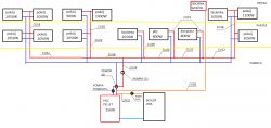
    Hello. Can anyone comment on the correctness of the sections in such an installation. I want to remake my old 2-inch installation and replace the stove. It is mainly about pipe diameters. I have a stove selected and the output from the stove is on G1.
    Selection of the diameter of copper pipes in the central heating installation
  • ADVERTISEMENT
  • #10 19361484
    Gargamelektro
    Level 15  
    Dear Arch18,

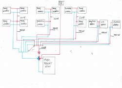
    not referring to the number of risers (not knowing the house plan and if you are not planning major renovations - it will probably stay that way) in the last diagram I noticed:
    1. a new heating system with a gas boiler requires a closed (pressurized) system - so you will not need a riser with an expansion tank;
    2. you will not need a 4-way valve - the gas boiler will maintain the set temperature;
    3. if there is no hydraulic coupling in the diagram, 2 central heating pumps are unnecessary - with the planned installation, a pump in the boiler is sufficient.
  • #11 19361678
    arch18
    Level 2  
    Hello, the boiler will not be gas, but pellet, so I wanted to stay with the open system

    Added after 27 [minutes]:

    I also considered such a solution, but I'm afraid of narrowings on the pex connectors. These 5 pieces, unfortunately, have to be because they are now distributed. I wonder which solution will be better. Selection of the diameter of copper pipes in the central heating installation

Topic summary

The discussion revolves around selecting the appropriate diameter of copper pipes for a central heating installation in a well-insulated house of approximately 110m2. The user is replacing an old steel system with copper and has received conflicting advice from plumbers regarding pipe sizes and radiator specifications. Key considerations include the total heating demand of 13474W, the layout of the house with multiple radiators on two floors, and the limitations of the existing riser configuration. Participants emphasize the importance of calculating power demand for each radiator, ensuring adequate pipe diameter to minimize flow resistance, and avoiding small cross-sections to prevent high pressure and water hammer issues. Recommendations include using larger diameters for supply pipes and considering flow velocities to optimize system performance.
Summary generated by the language model.
ADVERTISEMENT